
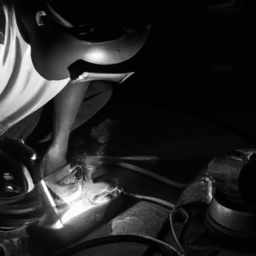
Shielded Metal Arc Welding (SMAW), commonly known as stick welding, remains a foundational process in metal fabrication due to its versatility and robust performance across diverse environments. This method employs a flux-coated consumable electrode to establish an electric arc, generating intense heat that melts both the electrode and the base metal, forming a durable weld joint. Achieving consistent, high-quality welds requires a precise understanding of several critical parameters and techniques.
Effective stick welding relies heavily on the operator’s ability to control variables such as amperage, arc length, electrode manipulation, and travel speed. Each element directly influences the weld bead’s shape, penetration, and mechanical properties. Mastering these fundamentals ensures structural integrity and aesthetic quality in finished work.
Electrode Selection: 6010 and 7018
Choosing the correct electrode is paramount for successful stick welding, with E6010 and E7018 being two of the most prevalent types, each possessing distinct characteristics and applications. The American Welding Society (AWS) classification system provides a standardized method for identifying these electrodes, detailing their tensile strength, welding positions, and coating types. Understanding these designations is crucial for optimal performance.
E6010 electrodes are characterized by a high-cellulose coating and are primarily designed for direct current electrode positive (DCEP) operation. They produce a forceful, deeply penetrating arc with an agitated weld pool, making them ideal for welding through contaminated, rusty, or painted surfaces. This electrode’s fast-freezing slag and deep penetration capabilities are particularly advantageous for root passes in pipe welding and general structural fabrication, yielding a flat bead with coarse ripples and easily removable slag. However, the cellulose coating introduces hydrogen into the weld, which can increase the risk of cracking in certain applications.
Conversely, E7018 electrodes feature a low-hydrogen, iron powder coating, suitable for both alternating current (AC) and direct current (DC) reverse polarity (DCEP) applications. These electrodes are renowned for their smooth, stable arc, minimal spatter, and excellent deposition rates, producing X-ray quality welds with superior mechanical properties. The low-hydrogen composition significantly reduces the risk of cracking and porosity, making E7018 a preferred choice for critical structural and heavy-duty welding, including pressure vessels, pipelines, and shipbuilding. They yield a smooth, uniform bead with easy slag removal.
The table below outlines key technical parameters for E6010 and E7018 electrodes, highlighting their differences for informed selection.
Mastering Amperage Settings
| Parameter | E6010 Electrode | E7018 Electrode |
|---|---|---|
| AWS Classification | E6010 | E7018 |
| Tensile Strength (min) | 60,000 psi | 70,000 psi |
| Coating Type | High Cellulose | Low Hydrogen, Iron Powder |
| Current Type | DC Positive (DCEP) | AC or DC Reverse Polarity (DCEP) |
| Penetration | Deep, Forceful | Medium |
| Slag Characteristics | Fast-freezing, thin, easily removable | Easy removal, smooth |
| Typical Applications | Root passes, dirty metal, pipe welding | Structural, heavy-duty, critical joints |
Accurate amperage adjustment is fundamental to achieving sound stick welds, directly influencing heat input, penetration, and bead profile. A common guideline suggests approximately 40 Amps per 1 mm of electrode diameter, or 1 Amp per 0.001 inch of electrode diameter, serving as a reliable starting point. For instance, a 1/8-inch (3.2 mm) electrode typically operates within a range of 90-130 Amps.
Several factors necessitate amperage adjustments beyond these general rules. Thicker base metals act as significant heat sinks, requiring higher amperage to maintain a molten puddle and ensure adequate penetration. Conversely, welding in vertical or overhead positions often demands a 10% to 15% reduction in amperage to prevent the weld puddle from sagging or falling out due to gravity.
The audible feedback from the arc provides crucial insight into proper amperage settings. An ideal arc produces a steady ‘bacon frying’ sound, indicating a balanced heat input. A distinct hiss suggests insufficient amperage, leading to poor penetration and electrode sticking, while a loud roar indicates excessive amperage, which can cause burn-through, undercut, and excessive spatter. Fine-tuning amperage based on these auditory cues and visual puddle behavior is a hallmark of skilled welding.
Striking and Maintaining the Arc
Initiating a stable electric arc is a foundational skill in stick welding, requiring precision to prevent the electrode from sticking to the workpiece. Two primary methods are employed: the ‘scratch’ method and the ‘tap’ method. The scratch method involves lightly dragging the electrode tip across the base metal, similar to striking a match, then quickly lifting it to establish the arc. This technique is often easier for beginners and when using AC welding machines.
Alternatively, the tap method entails quickly tapping the electrode onto the workpiece and immediately lifting it a short distance to ignite the arc. Regardless of the method, the goal is to create a consistent arc gap. The correct arc length is generally equivalent to the electrode’s core wire diameter; for example, a 1/8-inch electrode requires approximately a 1/8-inch arc length.
Maintaining a consistent arc length is challenging because the electrode continuously melts and shortens during welding. Welders must steadily lower the electrode towards the weld pool to compensate for this consumption. An excessively long arc can lead to instability, increased spatter, and porosity, while an arc that is too short risks the electrode sticking or ‘freezing’ to the base metal. The electrode should be held at a 20-30 degree drag angle relative to the direction of travel.
Terminating a weld properly is as important as striking the arc. As the weld approaches its end, holding the arc momentarily over the crater helps to fill it, preventing crater cracks. The electrode should then be quickly snapped away from the workpiece to efficiently break the arc and avoid unwanted arc strikes outside the weld zone.
Puddle Control and Travel Speed
Controlling the molten weld puddle and maintaining a consistent travel speed are critical for achieving uniform bead appearance, adequate penetration, and structural integrity. Travel speed refers to the rate at which the electrode moves along the joint, typically measured in inches per minute (IPM). For stick welding, a general range of 6-10 IPM is often recommended, with a 3.2mm electrode performing well at 6-8 IPM.
Moving the electrode too quickly results in a narrow, ropey bead with insufficient heat input, leading to lack of fusion, poor penetration, and undercut along the weld edges. The arc may not have adequate time to melt the base material, compromising the weld’s strength. Conversely, a travel speed that is too slow introduces excessive heat, causing the weld puddle to become wide, flat, or convex, increasing the risk of burn-through on thinner materials and promoting warping. Slow travel can also lead to excessive weld buildup, overlapping, and can even reduce penetration as a large puddle ‘cushions’ the arc.
Optimal travel speed is indicated by a weld bead that maintains a consistent width, exhibits smooth, even ripples, and resembles a quarter-moon shape. The molten puddle should follow the arc smoothly, with the arc ideally positioned in the leading one-third of the weld pool. Adjustments to travel speed must also consider material thickness, with thicker sections requiring slower movement for full penetration and thinner materials demanding faster speeds to prevent overheating. Maintaining a consistent drag angle, typically 15-20 degrees, further aids in proper puddle control and slag management.
Post-Weld Slag Management
Slag, the hard, glassy byproduct formed from the electrode’s flux coating and impurities, serves to protect the molten weld pool from atmospheric contamination during cooling. However, once the weld has solidified, this protective layer must be thoroughly removed to ensure the weld’s cleanliness, strength, and suitability for subsequent passes or inspection. Incomplete slag removal can lead to critical defects such as slag inclusions, which compromise the weld’s mechanical properties and can result in failure.
The primary tools for slag removal include a chipping hammer and a stiff wire brush. A chipping hammer, featuring both a flat chisel and a pointed pick, is used to break away the bulk of the slag. It is crucial to use controlled, light taps along the weld bead, focusing on the edges where slag often lifts most easily, rather than heavy blows that could damage the weld metal. Following the chipping process, a wire brush effectively removes any remaining loose particles and fine residue, preparing the surface for inspection or further welding.
For stubborn or heavy slag, an angle grinder fitted with a wire wheel or flap disc can be employed, though care must be taken to avoid grinding into the weld bead itself. In industrial settings, pneumatic or electric needle scalers are utilized for efficient removal from large or hard-to-clean surfaces. For multi-pass welds, meticulous interpass cleaning is indispensable. Each completed pass must be entirely free of slag and loose particles before the next layer is deposited, preventing the entrapment of impurities that could lead to porosity and other defects. This rigorous cleaning regimen between passes is a cornerstone of high-quality, multi-layer welding.