
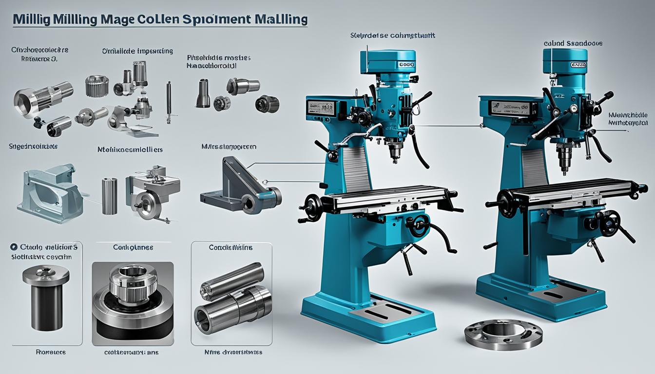
Milling machines are fundamental tools in subtractive manufacturing, precisely shaping workpieces by rotating multi-tooth cutters. These versatile machines are critical across industries like automotive, aerospace, and medical device manufacturing, producing parts with intricate geometries and high dimensional accuracy. Understanding the core components of a milling machine is essential for effective operation and maintenance.
Modern milling machines, whether manual or CNC, share a common anatomical structure designed for rigidity, precision, and efficient material removal. Each part plays a specific role in supporting the cutting process, from the foundational base to the intricate spindle drive and coolant delivery systems. The interplay of these components dictates the machine’s overall performance and capabilities.
Base Column and Knee
The base serves as the foundational structure of the milling machine, providing stability and absorbing vibrations generated during machining operations. Typically constructed from heavy cast iron, the base’s mass and material properties contribute significantly to the machine’s static rigidity and dynamic stiffness.
Rising vertically from the base is the column, often referred to as the machine’s backbone. This robust cast iron structure houses the driving mechanisms for the spindle and table feed, and its precisely machined vertical face provides guideways for the knee. The column’s hollow interior frequently accommodates the motor and drive system components.
Attached to the front of the column, the knee is a rigid casting that moves vertically along the column’s guideways. This vertical movement, controlled by an elevating screw, allows for precise adjustment of the distance between the cutting tool and the workpiece, directly influencing the depth of cut. The knee supports the saddle and worktable assembly.
Knee locks are crucial mechanisms that secure the knee rigidly in position once the desired vertical height is set. This clamping action prevents unwanted movement during machining, which is vital for maintaining dimensional accuracy and surface finish. The knee’s internal gearing mechanism facilitates its vertical adjustments.
Saddle and Worktable
| Taper Type | Taper Ratio | Spindle Contact | Typical RPM Range | Primary Application |
|---|---|---|---|---|
| CAT (V-Flange) | 7:24 | Taper Only | 8,000-12,000 | North American Standard, Heavy Machining |
| BT (Metric V-Flange) | 7:24 | Taper Only | 8,000-12,000 | Asian/European Standard, General Machining |
| HSK (Hollow Shank) | 1:10 | Taper & Face | >15,000 | High-Speed Machining, Precision Work |
The saddle is a sliding casting mounted atop the knee, providing transverse movement, commonly known as the Y-axis, to the worktable. It moves along guideways machined into the knee, enabling the cutter to reach different areas of the workpiece.
Resting on the saddle, the worktable is a rectangular casting designed to hold the workpiece or work-holding devices such as vises and fixtures. It provides longitudinal movement, the X-axis, and is equipped with multiple T-slots for secure clamping.
The worktable’s flatness tolerance is a critical specification for achieving precision in machined parts. Standard production machining typically aims for tolerances around ±0.010 inch (±0.25mm), while precision applications, such as aerospace or medical components, may require tighter tolerances down to ±0.002 inch (±0.05mm).
Modern milling machines often incorporate power feed mechanisms for the X, Y, and Z axes, ensuring consistent feed rates that are essential for optimal surface finish and extended tool life. These mechanisms, often located within the knee, allow for both manual and automated control of table movement.
Overarm and Arbor Support
The overarm is a horizontal structural component extending from the top of the column, particularly prominent in horizontal milling machines. It slides on dovetail ways on the column’s upper surface and is primarily designed to reinforce the arbor.
The arbor is a critical shaft that extends from the machine’s spindle, serving as the mounting point for various milling cutters. It features a tapered shank for precise alignment with the spindle’s taper hole and a threaded end to secure the arbor nut and cutter assembly.
Arbors are available in standard diameters, commonly 7/8, 1, 1 1/4, and 1 1/2 inches, and various lengths to accommodate different cutter sizes and machining requirements. They are typically splined, utilizing keys to lock cutters securely to the shaft, preventing slippage during heavy cuts.
The arbor support, suspended from the overarm, provides crucial outboard support for the arbor, especially during heavy-duty milling operations. This support typically contains a bearing that allows the arbor to rotate freely while maintaining rigidity, minimizing deflection and vibration.
Spindle Motor Drive
The spindle is the rotating shaft that directly holds and drives the cutting tool, transferring power from the motor to the tool. It is a precision component supported by high-quality bearings within the spindle head, which can often tilt for angular machining in vertical mills.
Spindle motor drives vary significantly, from traditional belt-driven systems to modern direct-drive configurations. Direct-drive spindles offer higher rigidity and better dynamic response, crucial for high-speed machining, while belt drives can provide vibration damping and easier speed changes. The motor’s power directly influences the machine’s material removal capabilities.
Tool holders interface with the spindle via standardized tapers, ensuring accurate and repeatable tool positioning. The most common taper families include CAT (V-Flange), BT (Metric V-Flange), and HSK (Hollow Shank Taper). Each system has distinct characteristics regarding rigidity, balance, and performance at varying spindle speeds.
HSK tool holders, with their shallow 1:10 taper and simultaneous face and taper contact, offer superior rigidity and repeatability, making them ideal for high-speed machining applications above 15,000 RPM. In contrast, CAT and BT holders, with their 7:24 steep taper, are well-suited for heavy cutting at moderate speeds.
Coolant Pump Assembly
The coolant pump assembly is an integral part of any modern milling machine, responsible for delivering cutting fluid to the machining zone. This system is crucial for managing heat, lubricating the cutting interface, flushing away chips, and improving surface finish.
Coolant pumps are designed to provide specific flow rates and pressures, which vary based on the machining operation and material. High-pressure coolant (HPC) systems, capable of delivering fluids at 1,000 to 3,000 psi, are increasingly common, offering enhanced chip control, improved heat dissipation, and superior surface finishes, especially for deep drilling or milling.
Cutting fluids themselves come in various types, including straight oils, soluble oils, semi-synthetics, and synthetics, each with distinct properties. Soluble oils, mixed with water, are common for general milling due to their balanced cooling and lubricating characteristics. Synthetic fluids excel in cooling for high-speed applications.
A robust coolant filtration system is essential to maintain fluid integrity and extend tool life. These systems remove contaminants like metal chips, grinding swarf, and abrasive particles from the coolant before recirculation. Filtration methods include gravity media filters, magnetic separators, vacuum filters, and hydrocyclones, ensuring clean coolant for consistent machining accuracy.