
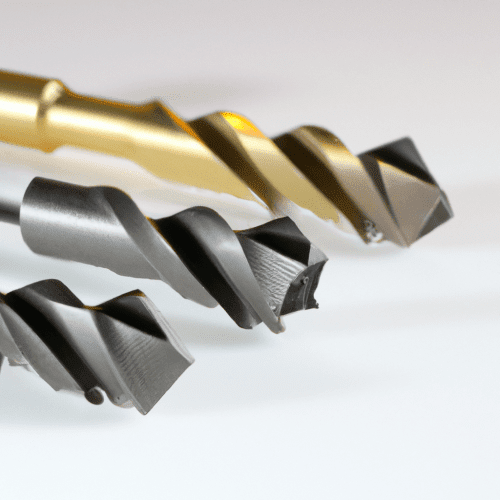
Milling operations rely on a diverse array of cutting tools, each engineered for specific material removal tasks and surface finish requirements. Understanding the distinct characteristics and applications of these cutters is fundamental for optimizing machining processes and achieving desired part specifications.
This technical guide explores the primary types of milling cutters: flat end mills, ball nose end mills, corner radius cutters, face mills, and fly cutters, detailing their geometry, typical uses, material considerations, standard tolerances, and critical feeds and speeds parameters.
Flat End Mills
Flat end mills, often referred to as square end mills, feature a cylindrical body with cutting edges on both their end and sides, making them highly versatile. While typically described as ‘square,’ most standard tools incorporate a slight corner radius, often around 0.002 inches (0.05 mm), to enhance edge strength and prevent premature chipping.
These cutters excel in creating slots, profiling perimeters, pocketing, and performing both roughing and finishing operations. Their geometry is ideal for producing sharp, intricate features and precise flat-bottomed grooves in a workpiece.
Commonly fabricated from High-Speed Steel (HSS) or solid carbide, flat end mills frequently utilize advanced coatings to boost performance. Titanium Aluminum Nitride (TiAlN) and Aluminum Chromium Nitride (AlCrN) coatings offer superior thermal stability and wear resistance for demanding applications, while Titanium Nitride (TiN) suits general-purpose machining in softer materials. For aluminum, Titanium Diboride (TiB2) is a specialized coating that prevents material adhesion.
Standard carbide flat end mills typically maintain a cutting diameter tolerance of +0.000/-0.002 inches (+0.000/-0.0508 mm). Shank diameters are held to even tighter specifications, generally ranging from -0.0001/-0.0004 inches (-0.00254/-0.01016 mm).
Optimal feeds and speeds for flat end mills are contingent on the workpiece material, tool composition, coating, and the specific depth of cut. For instance, aluminum machining often benefits from 2-3 flutes to facilitate chip evacuation, whereas steel and stainless steel typically require 4 or more flutes for enhanced edge strength and improved finish. Employing higher helix angles can also contribute to smoother shearing action and a superior surface finish.
Ball Nose End Mills
Ball nose end mills are distinguished by their spherical cutting tip, which enables the creation of smooth, continuous contoured surfaces. These tools are inherently center-cutting, allowing them to plunge directly into the material without pre-drilling.
Their primary application lies in 3D contouring, surface finishing, and mold and die manufacturing, where they produce blended surfaces with minimal tool marks. The unique tip geometry is crucial for achieving high-quality finishes on complex curved geometries.
These cutters are typically manufactured from ultra-micro grain carbide, providing exceptional hardness and consistent performance across materials like steel, stainless steel, and superalloys. Various advanced coatings, including AlTiN, TiAlN, TiAlSiN, AlCrN, AlCrSiN, and DLC, are applied to enhance wear resistance and prolong tool life.
Ball nose end mills are designed with high precision, often featuring a ball radius tolerance as tight as ±0.005 mm. The cutting diameter tolerance for these tools generally falls within +0.000/-0.002 inches (+0.000/-0.0508 mm).
When operating near the tool’s center axis, the effective cutting speed approaches zero, which can lead to rubbing and excessive heat generation. Consequently, a significant reduction in feed rate is necessary when engaging the workpiece near the tool’s rotational center. Careful consideration of step-over and step-down values is also vital for achieving the desired surface finish and optimizing machining time.
Corner Radius Cutters
Corner radius cutters, also known as bull nose end mills, feature a flat bottom combined with a precisely defined radius at the intersection of the cutting edge and the end face. This rounded corner replaces the sharp, fragile edge of a square end mill, significantly increasing tool strength and resistance to chipping.
These versatile tools are suitable for both roughing and finishing operations, offering benefits such as reduced tool wear and improved surface finish. They are particularly advantageous in mold and die work for blending features and enhancing fracture resistance by distributing cutting forces over a larger area.
Like other high-performance end mills, corner radius cutters are predominantly made from solid carbide and benefit from coatings such as TiAlN or AlCrN. These coatings contribute to increased durability and sustained performance, especially when machining tough materials.
The radius tolerance on corner radius end mills is typically ±0.001 inch (±0.0254 mm). When accounting for both corner radii and the flat section, the cutter diameter tolerance can be approximately +/- 0.004 inches (+/- 0.1016 mm).
Corner radius end mills can often be run at higher feeds and speeds compared to square end mills due to their enhanced strength. However, for accurate feed calculations, the ‘minor diameter’ (the nominal outer diameter minus twice the corner radius) should be considered the effective cutting diameter. A common practice involves reducing the spindle speed by 10-15% relative to standard parameters for the nominal size, coupled with a proportional decrease in feed per tooth.
Face Mills
Face mills are large-diameter cutting tools characterized by multiple indexable inserts mounted on a robust rotating body. The replaceable nature of these inserts makes face mills a cost-effective and adaptable solution for various machining tasks.
These cutters are primarily employed for machining large, flat surfaces, delivering high material removal rates and achieving smooth finishes. Face milling is essential for preparing surfaces for subsequent operations and ensuring the dimensional accuracy of components.
Inserts for face mills are available in diverse shapes, including round, square, and triangular, and are manufactured from carbide with specialized coatings. Positive rake inserts are preferred for softer materials and applications requiring lower cutting forces, while negative rake inserts provide greater durability for harder materials and heavy roughing operations.
Achieving excellent flatness and surface finish is a key objective in face milling. Standard CNC face milling operations typically yield a surface roughness (Ra) between 1.6–3.2 µm (63–125 µin), with fine milling capable of reaching Ra 0.8 µm (32 µin).
Optimized insert geometry and precise adjustment of feed per tooth (fz) are critical for improving surface roughness and extending insert life. High-productivity applications often utilize fast-feed cutters, which feature specialized geometries to remove smaller chips at elevated speeds.
Fly Cutters
A fly cutter is a single-point cutting tool, often equipped with one or two replaceable inserts, mounted in a holder that generates a large swept diameter. This tool’s straightforward design allows for a broad cutting path with a single active cutting edge.
Fly cutters are effective for machining large, flat surfaces, particularly in small batch production or on machines with less rigidity. They are also valued for their ability to produce fine finishes and custom surface textures on workpieces.
The cutting bits for fly cutters are typically made from High-Speed Steel (HSS) or carbide inserts, selected based on the workpiece material and the desired surface quality. While coatings can be applied to inserts, many fly cutters utilize uncoated HSS or carbide for their simplicity and effectiveness.
These tools are generally suited for mild cutting operations rather than heavy material removal due to potential issues with balance and vibration. Maintaining proper balance of the cutter assembly is paramount to prevent chatter and ensure a high-quality surface finish.
Feeds and speeds for fly cutters are determined by the cutting material, the required finish, and the overall rigidity of the machine setup. Due to their single-point cutting action and large swept diameter, conservative feed rates are often employed to preserve surface quality and mitigate vibration.
Milling Cutter Technical Parameters Comparison
| Cutter Type | Primary Application | Typical Material | Common Coatings | Surface Finish (Ra µm) | Diameter Tolerance (mm) |
|---|---|---|---|---|---|
| Flat End Mill | Slotting, profiling, pocketing | Carbide, HSS | TiAlN, AlCrN, TiN, TiCN, TiB2 (for Al) | 1.6 – 3.2 (standard milling) | +0.000/-0.0508 (+0.000/-0.002″) |
| Ball Nose End Mill | 3D contouring, surfacing, mold making | Micro-grain Carbide | AlTiN, TiAlN, TiAlSiN, AlCrN, AlCrSiN, DLC | 0.8 – 1.6 (fine milling) | ±0.005 (radius tolerance) |
| Corner Radius Cutter | Roughing, finishing, tool wear reduction | Carbide | TiAlN, AlCrN | 0.8 – 1.6 (fine milling) | ±0.0254 (radius tolerance ±0.001″) |
| Face Mill | Large flat surface machining, high material removal | Carbide inserts (on steel body) | Various for inserts (e.g., PVD/CVD for steel, cast iron) | 0.8 – 3.2 (fine to standard milling) | N/A (primarily surface flatness) |
| Fly Cutter | Small batch facing, custom finishes, large surfaces | HSS or Carbide inserts | Uncoated, or standard insert coatings | 0.8 – 1.6 (can achieve fine finishes) | N/A (primarily surface flatness) |