
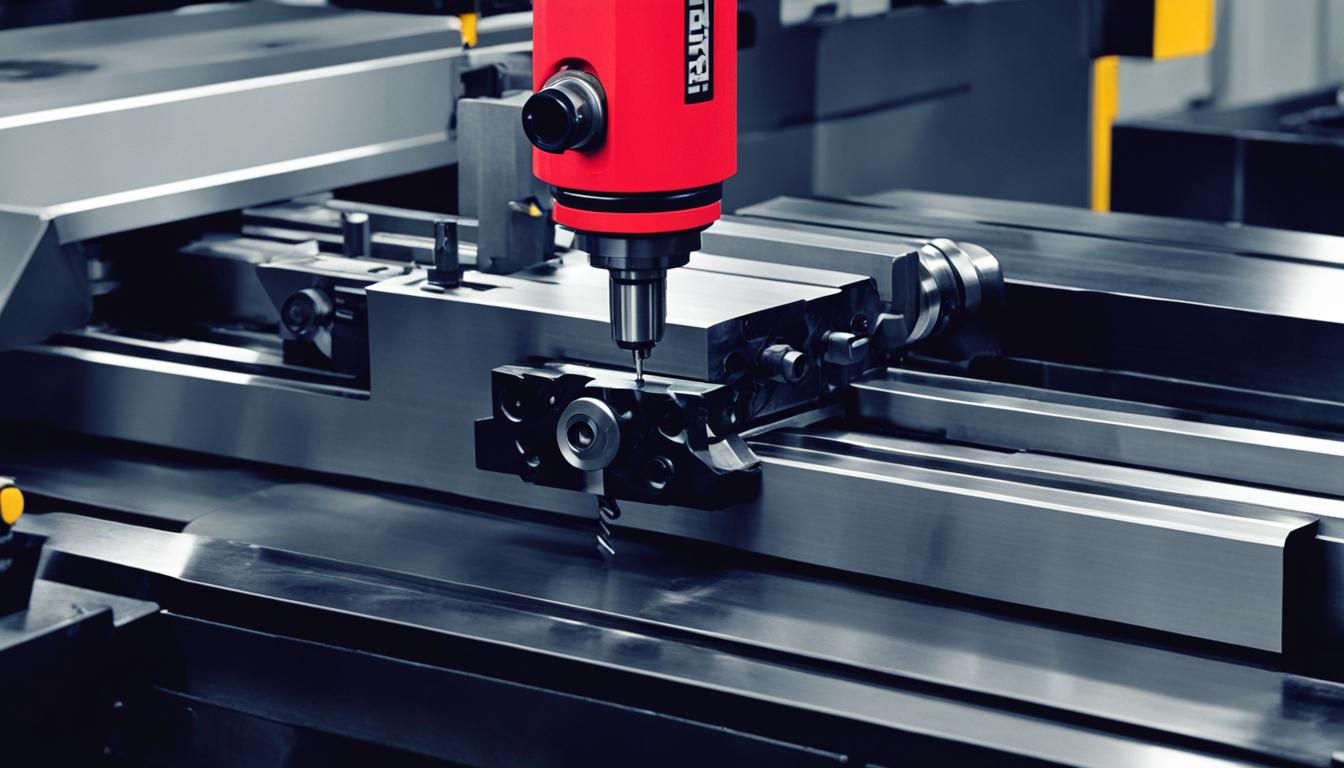
Facing and turning are fundamental machining processes performed on lathes, critical for shaping cylindrical workpieces with high precision. These subtractive manufacturing techniques involve rotating a workpiece against a stationary, single-point cutting tool to remove material. The controlled interaction between the tool and the rotating part allows for the creation of precise geometries and surface finishes.
Modern CNC lathes execute these operations with exceptional accuracy and repeatability, driven by computer programs that dictate tool movements along defined axes. This automation significantly enhances productivity and consistency in manufacturing.
Fundamentals of Lathe Machining Operations
A CNC lathe is a precision machine tool designed to shape materials by rotating a workpiece around a central axis while a cutting tool removes material. The workpiece is securely held in a chuck or collet, and the spindle motor provides the rotational motion.
Tool movement on a lathe is typically defined by two primary axes: the X-axis, which controls radial movement (perpendicular to the spindle axis), and the Z-axis, which governs longitudinal movement (parallel to the spindle axis). This two-axis control enables the creation of various cylindrical and flat features.
Key components of a CNC lathe include the robust bed, which forms the machine’s foundation, the headstock containing the spindle, and the tailstock for supporting longer workpieces. The tool turret holds multiple cutting tools, allowing for automatic tool changes during complex machining cycles.
The inherent precision and versatility of CNC lathes make them indispensable across diverse industries, including aerospace, medical, and automotive manufacturing. They are ideal for producing parts with rotational symmetry and tight dimensional controls.
Facing: Precision Flat End Surface Machining
| Material | Cutting Speed (SFM) | Roughing Feed Rate (IPR) | Finishing Feed Rate (IPR) |
|---|---|---|---|
| Aluminum 6061 | 600-1200 | 0.004-0.010 | 0.002-0.005 |
| Mild Steel (e.g., 1018) | 200-400 | 0.003-0.008 | 0.001-0.003 |
| Stainless Steel 304 | 100-150 | 0.002-0.005 | 0.001-0.002 |
Facing is a lathe operation that creates a flat, smooth, and perpendicular surface on the end of a workpiece. This process is essential for establishing a true reference plane, ensuring subsequent machining operations are accurate and square to the part’s rotational axis.
During facing, the single-point cutting tool moves radially across the rotating workpiece, typically starting from the outside diameter and feeding towards the center, or vice-versa. The tool’s path ensures uniform material removal across the entire face.
Achieving the desired surface finish in facing operations is critical, especially for sealing surfaces or mating components. Standard stock finishes often feature a continuous spiral groove, resulting in a roughness average (Ra) between 3.2 and 12.5 micrometers.
For smoother finishes, such as those used with metal gaskets, tool marks should be imperceptible to the naked eye, targeting an Ra between 3.2 and 6.3 micrometers. These finishes are achieved with specific tool nose radii and controlled feed rates.
Turning: Cylindrical Outer Diameter Reduction
Turning is the process of reducing the outer diameter of a workpiece to a specified dimension and shape. This operation is fundamental for creating shafts, pins, bushings, and other components requiring precise cylindrical features.
The cutting tool moves longitudinally along the Z-axis, parallel to the workpiece’s rotational axis, removing material in controlled passes. This can involve external turning, taper turning to create conical shapes, or contour turning for complex profiles.
Standard commercial tolerances for CNC turning typically range from ±0.05 mm to ±0.1 mm for general diameter features. For applications demanding higher precision, such as bearing fits or sealing surfaces, tolerances can be tightened to ±0.005 mm to ±0.02 mm.
Runout tolerance is a critical geometric control for turned shafts, specifying the permissible deviation of a surface from its intended axis of rotation. Circular runout controls individual cross-sections, while total runout governs the entire surface, ensuring coaxiality and preventing wobble in rotating components.
Optimal feeds and speeds are crucial for efficient turning, impacting surface finish, tool life, and material removal rates. These parameters vary significantly based on the workpiece material and cutting tool. For instance, aluminum generally allows for higher cutting speeds than steel.
Single-Point Cutting Tools
Single-point cutting tools are characterized by having only one cutting edge in contact with the workpiece at any given time. These tools are fundamental for turning, facing, boring, and threading operations on lathes.
The geometry of a single-point tool significantly influences its cutting performance, chip formation, heat dissipation, and the resulting surface finish. Key geometric parameters include the rake angle, relief angle, cutting edge angle, and nose radius.
A positive rake angle generally reduces cutting forces and improves chip flow, suitable for softer materials, while a negative rake angle provides greater edge strength for harder materials or interrupted cuts. Relief angles prevent the tool from rubbing against the workpiece, minimizing friction and heat.
The nose radius, the small radius at the tool’s tip, plays a crucial role in surface finish and tool strength. A larger nose radius typically produces a smoother finish but can increase cutting forces, whereas a smaller radius offers sharper cutting but is more prone to wear.
Modern single-point cutting tools are often made from advanced materials to withstand high temperatures and wear. Common materials include:
- Coated cemented carbide inserts
- High-speed steel (HSS)
- Ceramics
- Cubic Boron Nitride (CBN)
- Polycrystalline Diamond (PCD)
Indexable inserts, which are replaceable cutting tips, are widely used for their efficiency and ability to maintain accuracy while reducing setup time.
Workpiece Setup and Alignment
Secure workpiece setup is paramount in lathe operations to ensure stability, concentricity, and prevent runout, which can lead to inaccuracies and poor surface finishes. The workholding device, typically a chuck or collet, must firmly grip the material.
Three-jaw self-centering chucks are common for round or hexagonal parts, offering quick setup as all jaws move simultaneously. Four-jaw independent chucks provide greater versatility and precision, allowing individual jaw adjustment for irregular shapes and finer centering.
Collet chucks are ideal for small-diameter and delicate parts, providing uniform pressure and excellent precision for tight tolerances. The choice between outer diameter (OD) gripping and inner diameter (ID) gripping depends on the workpiece geometry and machining sequence.
Proper alignment of the lathe’s headstock and tailstock is critical for producing parallel cuts and maintaining dimensional accuracy along the workpiece length. Misalignment can cause tapered features or excessive runout.
Alignment is typically verified using precision test bars and dial indicators, or increasingly, laser alignment systems for enhanced accuracy. For longer, more slender workpieces, additional support from a tailstock, steady rest, or follow rest is mandatory to prevent deflection and vibration during cutting.