
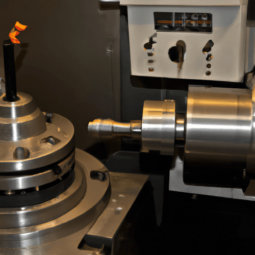
Computer Numerical Control (CNC) milling machines are fundamental to modern manufacturing, transforming raw materials into precision components across diverse industries. These sophisticated systems execute complex machining operations with high accuracy and repeatability, driven by programmed instructions. Understanding the intricacies of CNC milling, from initial setup to final inspection, is essential for producing high-quality parts efficiently.
CNC milling involves the removal of material from a workpiece using rotating multi-point cutting tools. The machine’s spindle rotates the tool at high speeds, while the workpiece moves relative to the tool, creating the desired geometry. This process is highly versatile, capable of working with a wide array of materials, including various metals and plastics.
Precision Vertical Mill Setup Procedures
Proper vertical mill setup is the cornerstone of accurate and efficient CNC machining. This critical phase involves securing the workpiece, ensuring machine alignment, and verifying spindle integrity. Neglecting these steps can lead to dimensional inaccuracies, poor surface finishes, and premature tool wear.
Workholding strategies are paramount for stability during machining. Common methods include vises, clamps, and custom fixtures, each chosen based on part geometry, material, and machining forces. Secure clamping prevents workpiece movement, which is vital for maintaining tight tolerances and achieving consistent results.
Spindle runout, the deviation of the spindle’s rotational axis from its ideal path, significantly impacts part quality and tool life. Acceptable radial runout for new precision Vertical Machining Centers (VMCs) should be ≤10μm (0.0004″), while standard machines typically allow up to 25μm (0.001″). Regular measurement with a dial test indicator and a precision test bar is crucial to monitor and maintain spindle accuracy.
Tramming the mill head ensures that the spindle is perfectly perpendicular to the worktable. This process involves using a dial indicator to measure the height variation across the table as the spindle rotates. Correct tramming is essential for achieving flat surfaces and accurate hole depths, preventing tapered features or uneven cuts.
Configuring Tool Offsets for Accuracy
| Tolerance Grade | Metric (mm) | Imperial (inches) | Typical Application |
|---|---|---|---|
| Standard Commercial | ±0.05 to ±0.13 | ±0.002 to ±0.005 | General mechanical components, housings |
| Precision Grade | ±0.01 | ±0.0004 | Mechanical components, automotive, consumer electronics |
| Ultra-High Precision | ±0.005 | ±0.0002 | Aerospace, medical devices, optical assemblies |
Tool offset configuration is a vital step in CNC programming, enabling the machine to compensate for the physical dimensions of cutting tools. This ensures that the programmed toolpath, often based on the part’s nominal geometry, translates into accurate material removal. Without proper offsets, parts would be consistently undersized or oversized.
Tool length offsets (TLO) account for the varying lengths of different cutting tools. Each tool’s length is measured from a reference point, typically the spindle face, to its tip. This measured value is then entered into the machine’s tool offset register, allowing the CNC control to adjust the Z-axis position automatically for each tool change. This eliminates the need to reprogram the Z-depth for every tool.
Cutter diameter compensation (CDC), often activated by G41 (left compensation) or G42 (right compensation) G-codes, adjusts the toolpath to account for the actual diameter of the milling cutter. This allows programmers to define contours based on the part’s final dimensions, rather than calculating the tool’s centerline path. The machine’s control system then offsets the tool by its radius, ensuring precise feature sizing.
Modern tool presetters offer advanced capabilities for measuring tool geometry offline, improving setup efficiency and accuracy. These devices precisely measure tool length and diameter, automatically transferring data to the CNC machine’s control. This reduces manual input errors and minimizes machine downtime, as tools are ready before being loaded into the spindle.
Ensuring Part Quality Through Inspection
Part quality inspection is an indispensable phase in CNC manufacturing, verifying that machined components conform to engineering drawings and specified tolerances. This systematic process begins even before machining, with design reviews, and continues through various stages of production.
Initial checks include First Article Inspection (FAI), a comprehensive dimensional verification of the first part produced in a new setup. In-process inspections involve operators using gauges and calipers at regular intervals to detect deviations early. Final inspection employs a range of metrology tools to ensure all specifications are met before shipment.
Coordinate Measuring Machines (CMMs) are essential for high-precision quality control, especially for complex geometries and tight tolerances. CMMs use sophisticated probes to capture three-dimensional geometric data from a part’s surface, comparing it against the original CAD model. This provides unparalleled accuracy and repeatability, generating detailed inspection reports.
Geometric Dimensioning and Tolerancing (GD&T) is a symbolic language used on engineering drawings to define allowable variations in form, orientation, and location. GD&T provides a more comprehensive control over part geometry than traditional dimensional tolerances, ensuring parts function as intended and are interchangeable. CMMs are particularly effective at validating GD&T callouts.
Standard CNC machining tolerances typically range from ±0.05 mm to ±0.13 mm for most milling operations. Achieving tighter tolerances, such as ±0.01 mm, requires careful process control, specialized equipment, and CMM inspection, significantly increasing costs.
Fundamentals of CNC Control Programming
CNC control programming dictates every movement and function of the milling machine, translating design intent into machine-readable instructions. G-code and M-code form the core of this programming language, enabling precise control over toolpaths, speeds, and auxiliary functions.
G-codes primarily define geometric movements and machining functions. Common G-codes include G00 for rapid traverse, G01 for linear interpolation (straight line cuts), and G02/G03 for circular interpolation (arc movements). These commands specify the tool’s path and feed rate, crucial for material removal.
M-codes control miscellaneous machine functions, such as spindle start/stop (M03/M05), coolant on/off (M08/M09), and program end (M30). While G-codes define ‘where’ and ‘how’ the tool moves, M-codes manage the machine’s operational aspects.
Computer-Aided Manufacturing (CAM) software plays a pivotal role in modern CNC programming. CAM systems automatically generate complex G-code from CAD models, optimizing toolpaths, simulating cuts, and detecting potential collisions. Advanced CAM features in 2026 include AI-driven toolpath suggestions, GPU-accelerated simulations, and enhanced multi-axis capabilities, significantly reducing programming time and improving efficiency.
Strategic Milling Cutter Selection
Selecting the appropriate milling cutter is critical for optimizing machining performance, achieving desired surface finishes, and maximizing tool life. Cutter geometry, material, and coatings must be carefully matched to the workpiece material and the specific machining operation.
End mills are versatile cutting tools distinguished by their ability to cut in all directions, unlike drills. They are classified by their construction material (e.g., High-Speed Steel, solid carbide), number of flutes, and end geometry. Common types include square end mills for straight walls and slots, ball end mills for 3D contours, and corner radius end mills for rounded corners.
Tool material selection directly impacts cutting performance. Solid carbide end mills offer superior hardness and heat resistance, making them ideal for machining harder materials and achieving higher speeds and feeds. High-Speed Steel (HSS) tools are more economical and suitable for softer materials or less demanding applications.
Feeds and speeds, the rate at which the tool moves into the workpiece and the rotational speed of the spindle, are crucial parameters. Incorrect settings can lead to poor surface finish, excessive tool wear, or tool breakage. Modern CAM software often provides optimized feeds and speeds, which can be further refined by machinists based on real-world conditions and material properties.
Advanced coating technologies, such as TiN, TiAlN, and AlTiN, enhance tool performance by increasing hardness, wear resistance, and lubricity. These coatings allow for higher cutting speeds and extended tool life, particularly when machining challenging materials like stainless steel or titanium. Selecting the right coating can significantly improve productivity and reduce manufacturing costs.