
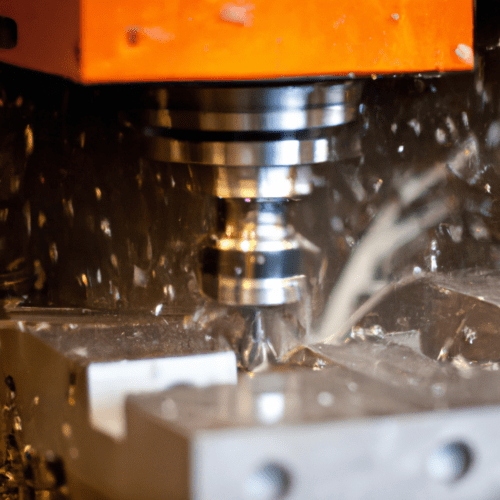
Computer Numerical Control (CNC) milling is a subtractive manufacturing process that precisely shapes raw material into a desired component by removing excess material with rotating multi-point cutting tools. This highly automated method relies on digital design data and sophisticated machinery to achieve intricate geometries and tight tolerances. It is a cornerstone of modern manufacturing across diverse industries, from aerospace to medical devices.
The core principle involves a workpiece securely held in place while a cutting tool, guided by computer commands, systematically removes material. This contrasts with additive manufacturing, which builds parts layer by layer. CNC milling excels in producing parts with superior surface finishes and dimensional accuracy, especially for traditional part shapes and when specific material properties are critical.
Subtractive Milling Workflow Explained
The subtractive milling workflow begins long before any material is cut, starting with a comprehensive digital design. Engineers create a detailed 3D model of the desired part using Computer-Aided Design (CAD) software, defining its geometry, features, and critical dimensions. This digital blueprint serves as the foundation for all subsequent manufacturing steps.
Following the CAD design, the model is imported into Computer-Aided Manufacturing (CAM) software. Here, a manufacturing engineer plans the machining strategy, selecting appropriate cutting tools, defining machining operations, and generating toolpaths. This critical phase translates the part’s geometry into a series of precise movements the CNC machine will execute.
Once the CAM programming is complete, the machine setup phase involves securing the raw material, or ‘workpiece,’ onto the machine’s table using workholding devices like vises or clamps. The selected cutting tools are loaded into the spindle or tool changer, and their physical dimensions are measured and entered into the machine’s control system as tool offsets.
With the machine prepared and programmed, the actual material removal process commences. The CNC machine executes the generated G-code, guiding the cutting tool along the defined toolpaths to progressively remove material from the workpiece. This continues until the component matches the exact specifications of the digital design.
CAM Path Generation Techniques
| Parameter | Standard Tolerance (Linear) | High-Precision Tolerance (Linear) | Standard Surface Finish (Ra) |
|---|---|---|---|
| General Machining (ISO 2768-m) | ±0.127 mm (±0.005 in) | ±0.025 mm (±0.001 in) | 3.2 μm (125 μin) |
| Precision Machining (ISO 2768-f) | ±0.05 mm (±0.002 in) | ±0.01 mm (±0.0004 in) | 0.8 μm (32 μin) |
| Ultra-Precision (Specialized) | N/A | ±0.0025 mm (±0.0001 in) or better | 0.2 μm (8 μin) or finer |
CAM software is indispensable for generating the precise toolpaths that direct a CNC machine’s movements. It intelligently analyzes the part’s geometry to create efficient cutting strategies, ensuring optimal material removal and surface quality. Programmers can apply various toolpath strategies, including contouring, pocketing, and drilling, depending on the part’s features.
Automated toolpath generation is a significant capability of advanced CAM systems. These systems can recognize common part features, such as holes and pockets, and automatically apply optimized machining strategies. This reduces manual programming time and enhances consistency across different parts.
Toolpath simulation within CAM software is a crucial step for verifying the machining process before physical cutting begins. It allows machinists to visualize the tool’s movement, identify potential collisions or programming errors, and fine-tune parameters like speed, feed rate, and depth of cut. This proactive approach minimizes scrap and prevents costly machine damage.
Post-processing is the final stage of CAM path generation, where the generic toolpath data is converted into machine-specific G-code. Advanced CAM software offers flexible and configurable post-processors to accommodate a wide variety of machine and control types, optimizing the G-code for faster and more efficient execution on the target CNC machine.
Tool Offset Configuration and Management
Tool offsets are critical parameters that bridge the gap between programmed toolpaths and the actual physical position of the cutting tool. They compensate for variations in tool length and diameter, ensuring that the machine accurately executes the G-code regardless of the specific tool loaded.
Tool length offsets (TLO) account for the distance from a spindle’s reference face to the tip of each cutting tool. This allows different tools with varying lengths to share the same Z-axis program without requiring manual adjustments or reprogramming. G43 is the common G-code for applying positive tool length compensation.
Diameter offsets, also known as cutter compensation, adjust the toolpath to account for the actual diameter of the cutting tool. This is particularly important for contouring operations, where the tool’s side engages the workpiece. Wear offsets further refine these values during production to compensate for gradual tool wear, maintaining dimensional accuracy over long runs.
Work offsets (e.g., G54-G59) define the location of the workpiece zero point relative to the machine’s home position. This allows multiple parts or setups on a single machine table, simplifying programming and setup procedures. Modern practices often involve using touch probes for automated, real-time measurement of both tool and work offsets, significantly reducing setup time and potential errors.
High-Speed Cutter Engagement Strategies
High-Speed Machining (HSM) combines very high spindle speeds with shallow depths of cut and controlled radial engagement to achieve faster cycle times, improved surface finishes, and predictable tool life. This is a system-level approach requiring harmony between the machine, tooling, CAM strategy, and fixturing.
A core strategy in HSM is maintaining a constant chip load by employing high-efficiency milling techniques. Tools engage the material at reduced radial depths, typically 10-30% of the cutter diameter. This lighter cut minimizes tool deflection and allows for significantly higher feed rates, often doubling or tripling conventional material removal rates.
Trochoidal milling is a prominent HSM technique, especially for roughing operations and slotting. The cutter follows a circular looping path, limiting radial engagement to a small arc. This prevents the tool from being ‘buried’ at 100% engagement, which can overload the cutter and lead to chatter or breakage.
Advanced CAM packages are optimized for HSM, generating toolpaths that incorporate these strategies. Adaptive clearing, for instance, automatically adjusts toolpaths to maintain a constant chip load, maximizing material removal rates while minimizing tool wear. Axial chip thinning also plays a role, particularly in deep slots, by tilting the approach to achieve greater depths without harmonic issues.
Part Inspection Phase
The part inspection phase is crucial for ensuring that machined components meet all specified dimensional and surface finish requirements. Quality control begins with a design review and print analysis, followed by rigorous checks throughout and after the machining process.
In-process inspection involves ongoing checks performed by operators using gauges and calipers at set intervals during production. This helps detect any deviations early, preventing an entire batch from going out of tolerance. For critical dimensions, automated touch probes integrated into the CNC machine can provide real-time measurements.
Post-process inspection employs advanced metrology equipment to verify the final part’s accuracy. Coordinate Measuring Machines (CMMs) are the ‘gold standard’ for dimensional inspection, providing highly accurate 3D measurements for complex geometries and tight tolerances. Optical comparators and various gauges are also used for specific feature verification.
Surface finish is another critical parameter, typically measured using a profilometer to determine the roughness average (Ra). Standard ‘as-machined’ finishes are often Ra 3.2 μm (125 μin), with tighter requirements like Ra 0.8 μm (32 μin) for smoother surfaces. Documentation of all measurements is essential for traceability and to provide objective evidence that parts meet specifications.