
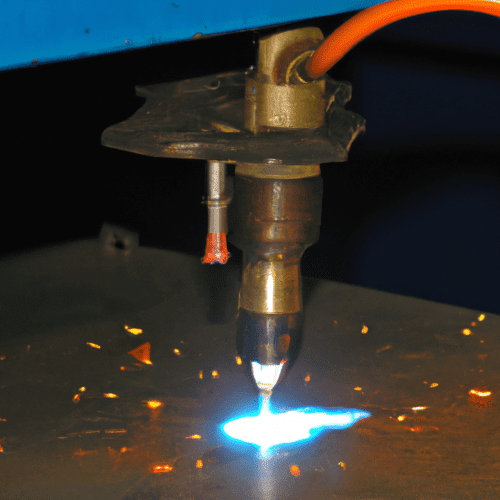
Plasma cutting technology utilizes an extremely hot, electrically conductive gas to sever metallic materials with precision. This process relies on several interconnected physical phenomena, transforming compressed air or other gases into a superheated plasma stream. The core principle involves creating an electrical arc that ionizes a gas, enabling it to conduct electricity and transfer intense thermal energy to the workpiece.
Compressed Air Ionization
The initial step in plasma generation involves introducing a gas, often compressed air, into the torch’s cutting head. This gas is directed through a small orifice, typically the nozzle, where it begins to constrict. The primary function of this gas is to serve as the plasma medium and to cool the torch components.
Ionization occurs when gas atoms lose or gain electrons, becoming electrically charged ions. In a plasma torch, a high-frequency, high-voltage spark is introduced, creating a conductive path within the gas. This spark strips electrons from the gas molecules, forming a localized region of ionized gas.
Air, composed primarily of nitrogen and oxygen, is a common plasma gas due to its availability and cost-effectiveness. When ionized, these gases contribute to the plasma’s thermal and electrical properties. The degree of ionization directly influences the plasma’s temperature and cutting efficiency.
High-Voltage Arc Ignition
| Material Type | Thickness (mm) | Amperage (A) | Typical Cut Speed (mm/min) | Plasma Gas |
|---|---|---|---|---|
| Mild Steel | 6 | 40 | 2500-3500 | Air/Oxygen |
| Mild Steel | 12 | 60-80 | 1500-2500 | Air/Oxygen |
| Mild Steel | 25 | 80-100 | 800-1500 | Air/Oxygen |
| Stainless Steel | 3 | 40-60 | 2000-3000 | Nitrogen |
| Stainless Steel | 12 | 80-100 | 800-1500 | Nitrogen/Ar-H |
| Aluminum | 3 | 40-60 | 2500-3500 | Air/Nitrogen |
| Aluminum | 12 | 80-100 | 1000-2000 | Nitrogen/Ar-H |
Arc ignition is initiated by a high-frequency (HF) or contact start system, generating a pilot arc. The HF system creates a momentary, high-voltage spark, typically between 3,000 to 10,000 V AC at 2 MHz, between the electrode and the nozzle, ionizing the gas within the torch. This pilot arc is a low-current, non-transferred arc that establishes the initial plasma channel.
Once the pilot arc is established, it provides a conductive path for the main cutting current. The power supply converts single or three-phase AC line voltage into a smooth, constant DC voltage ranging from 200 to 400VDC. When the torch is brought close to the workpiece, the main power supply transfers the arc from the electrode to the workpiece, creating the ‘transferred arc’. This transferred arc is significantly more powerful and stable, with pilot arc currents typically limited to 20-40 A DC.
This high voltage overcomes the dielectric strength of the gas, allowing current to flow. Modern systems often use non-HF starting to reduce electromagnetic interference (EMI), which can affect sensitive electronics like CNC controllers.
Plasma Gas Flow Dynamics
The plasma gas, whether air, oxygen, nitrogen, or a mixture, flows at high velocity through the torch nozzle. This constricted flow accelerates the gas, increasing its kinetic energy. The nozzle’s design is critical for shaping and focusing the plasma stream.
As the gas passes through the electric arc, it absorbs immense thermal energy, reaching temperatures up to 22,000°C (40,000°F). This superheating causes further ionization and expansion of the gas, transforming it into a true plasma state. The high velocity of the plasma jet is essential for efficient material removal.
Different plasma gases offer distinct advantages for specific materials. Oxygen plasma provides excellent cutting speeds and dross-free cuts on mild steel due to an exothermic reaction with the molten metal. Nitrogen is often used for stainless steel and aluminum, while argon-hydrogen mixtures are suitable for thick stainless steel and non-ferrous metals, offering the hottest burning plasma gas.
Metal Thermal Melting and Severing
The intensely hot and focused plasma jet impinges directly onto the workpiece surface. The extreme temperature of the plasma rapidly melts the metal at the point of contact. This localized melting is the primary mechanism for material removal.
Simultaneously, the high-velocity plasma stream mechanically blows away the molten metal, creating a ‘kerf’. The efficiency of this expulsion process is crucial for achieving clean cuts and minimizing dross formation. Proper torch height and travel speed are vital for optimal results, as incorrect settings can lead to various types of dross.
Standard tolerances for plasma cutting typically range from ±0.25 to ±0.75 mm (±0.010 to ±0.030 inches) for material thicknesses up to 25 mm (1 inch). Precision plasma systems can achieve tighter tolerances, especially on thinner materials, with average edge angularity of 1° to 3° depending on thickness.
Swirl Ring Airflow
A critical component in many plasma torches is the swirl ring, located within the torch head. This ring features precisely angled holes or channels that impart a rotational, swirling motion to the incoming plasma gas. This swirling action is fundamental to arc stability and cut quality.
The swirling gas creates a vortex around the central electrode and arc column. This vortex constricts the plasma arc, making it narrower and more focused. A tighter arc concentrates the thermal energy into a smaller area, increasing cutting power and precision.
Furthermore, the swirling airflow helps to cool the nozzle and electrode, extending their lifespan. It also assists in expelling molten metal from the kerf, preventing it from solidifying on the cut edge as dross. The design of the swirl ring directly impacts the plasma jet’s characteristics and overall cutting performance, with some systems even offering counter-clockwise swirl rings for ‘mirror cutting’ applications.
Plasma Cutting Parameters: A General Reference
Achieving optimal plasma cutting results requires careful consideration of several parameters, including amperage, cut speed, and gas selection. The following table provides general starting points for common materials and thicknesses. Actual settings may vary significantly based on the specific plasma system, consumables, and desired cut quality.
For mild steel, a common rule of thumb for a clean cut is approximately 1 amp per 0.025mm of thickness. Aluminum, with its high thermal conductivity, often requires higher speeds and sometimes lower amperages than steel of the same thickness to prevent warping and achieve a clean finish.