
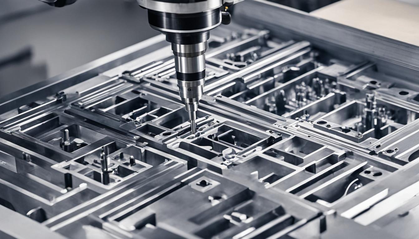
Successful CNC programming begins long before any G-code is written. A systematic approach to pre-programming steps ensures efficiency, accuracy, and ultimately, a high-quality finished part. Overlooking these foundational considerations can lead to costly errors, extended cycle times, and premature tool wear.
Analyzing Engineering Drawings
Thoroughly interpreting engineering drawings is the critical first step in any CNC machining project. These drawings provide all necessary geometric and dimensional information, including features, dimensions, tolerances, and surface finish requirements. Understanding every detail prevents misinterpretations that could lead to scrapped parts.
Key elements to scrutinize include datum features, which establish the coordinate system for the part, and geometric dimensioning and tolerancing (GD&T) callouts. GD&T specifies critical relationships between features, such as flatness, perpendicularity, and true position, ensuring functional fit and assembly.
Standard tolerances for CNC machining typically range from ±0.005 inches (±0.127 mm) for general features, with tighter tolerances of ±0.002 inches (±0.050 mm) or even ±0.001 inches (±0.025 mm) reserved for critical mating surfaces. Specifying unnecessarily tight tolerances increases machining time and cost.
Selecting Raw Material Stock
| Material | Tool Type | SFM (Carbide) | Chip Load (1/4″ End Mill) | Typical RPM (1/4″ End Mill) | Typical Feed Rate (IPM) |
|---|---|---|---|---|---|
| Aluminum 6061 | 2-3 Flute End Mill | 800-1000 | 0.003″-0.005″ | 12,224-15,280 | 73-229 (3 flutes) |
| Steel 1018 | 4 Flute End Mill | 300-400 | 0.001″-0.003″ | 4,584-6,112 | 18-73 (4 flutes) |
| Stainless Steel 304 | 4 Flute End Mill | 200-300 | 0.001″-0.003″ | 3,056-4,584 | 12-55 (4 flutes) |
Choosing the correct raw material stock is paramount, influencing machinability, part performance, and overall cost. Engineers must consider mechanical properties like strength, hardness, and corrosion resistance, alongside factors such as thermal and electrical conductivity.
Common metals for CNC machining include various aluminum alloys (e.g., 6061 for versatility, 7075 for high strength), stainless steels (e.g., 304 for general purpose, 316 for marine applications), and low carbon steels like 1018. Plastics such as Delrin (POM), Nylon, and Polycarbonate are also frequently machined.
Beyond the material type, the stock’s form and condition are vital. Options include bar stock, plate, billet, extrusions, or castings. Specifying the material’s condition, such as annealed, cold-worked, or heat-treated, significantly impacts its machinability and final properties.
Choosing Workholding Fixtures
Effective workholding is essential for maintaining workpiece stability and achieving desired precision throughout the machining process. The fixture must securely locate and clamp the part without deforming it, while also providing adequate tool access.
Various workholding methods exist, from universal vises and chucks to custom-designed modular or dedicated fixtures. The choice depends on part geometry, required precision, production volume, and material characteristics. Slim or flexible parts, for instance, demand distributed support to prevent warping.
Dedicated fixtures offer high repeatability and reduced setup times for high-volume production, while modular systems provide flexibility for lower volumes and diverse part types. Regardless of the type, ensuring rigidity and cleanliness of locating surfaces is critical to prevent inconsistent clamping and datum shifts.
Determining Tool Paths
Defining efficient and effective tool paths is a core aspect of CNC programming, directly impacting cycle time, tool life, and surface finish. This involves strategizing roughing, semi-finishing, and finishing operations.
Roughing operations prioritize rapid material removal using large tools, maximum feasible depth of cut, and higher feed rates, leaving a consistent allowance for subsequent passes. Modern adaptive tool paths maintain a constant tool engagement, allowing for higher feed rates without overloading the cutter.
Finishing strategies focus on achieving the specified surface finish and accurate final dimensions. This typically involves lighter cuts, optimized feeds and speeds, and often larger tools to minimize machining time and avoid unnecessary passes.
Calculating Speeds and Feeds
Accurately calculating speeds and feeds is fundamental to successful CNC machining, balancing material removal rates with tool life and surface quality. These parameters, expressed as spindle speed (RPM) and feed rate (IPM or IPR), are derived from the cutting speed (SFM) and chip load per tooth.
Cutting speed (SFM) is determined by the workpiece material and tool material, while chip load (feed per tooth) depends on the tool diameter, number of flutes, and material. Formulas for calculating RPM and feed rate are: RPM = (SFM × 3.82) / Tool Diameter (inch) and Feed Rate (IPM) = RPM × Number of Flutes × Chip Load per Tooth.
These values serve as starting points; real-world optimization involves listening to the cut, observing chip formation, and monitoring tool wear. Modern tooling and coatings can significantly increase recommended chip loads, while factors like minimum quantity lubrication (MQL) may require lower surface speeds.
Establishing Machine Zero (WCS)
Establishing the Work Coordinate System (WCS), or machine zero, is a fundamental step that defines the relationship between the CNC program’s origin and the physical workpiece on the machine. This allows the same program to be run at different fixture locations without modification.
CNC controls typically use G54, G55, G56, and so on, to define multiple work offsets. G54 is often the default. The programmer decides on a logical part origin (e.g., a corner, center, or specific datum feature) that aligns with the engineering drawing.
Machinists then use probes, edge finders, or indicators to measure the physical location of this chosen part origin relative to the machine’s home position. These measured values are entered into the corresponding G54, G55, or other work offset registers, effectively telling the machine where the part’s zero point is located.