
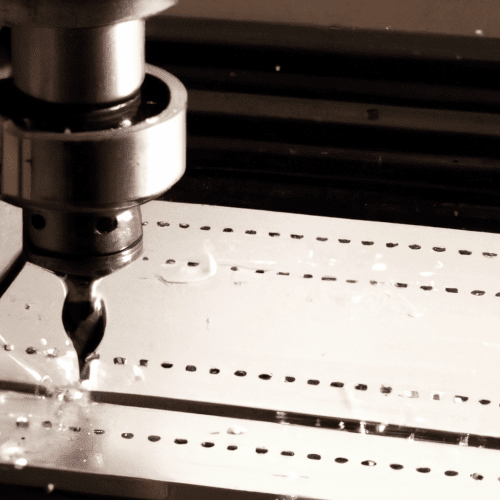
Milling is a subtractive manufacturing process employing rotary cutters to remove material from a workpiece, creating custom-shaped parts. This versatile machining method is fundamental across numerous industries, from aerospace to medical device manufacturing, due to its ability to produce complex geometries with high precision. Understanding the core mechanics of milling is essential for optimizing processes and achieving desired outcomes.
The process relies on the interaction between a rotating multi-point cutting tool and a stationary or moving workpiece. Material removal occurs through a combination of shear deformation and fracture, generating chips. Effective milling requires careful consideration of tool geometry, material properties, and machine kinematics to ensure efficiency and part quality.
Understanding Rotary Cutter Engagement
Rotary cutter engagement describes the dynamic interaction between the milling tool’s cutting edges and the workpiece material. Each cutting edge repeatedly enters and exits the material, creating intermittent loads. Managing these loads is critical for maximizing tool life, enhancing productivity, and ensuring process reliability.
The radial engagement, defined as the ratio of the radial depth of cut (ae) to the cutter diameter (Dc), significantly influences chip thickness and heat generation. A larger arc of engagement generally transfers more heat into the cutting edge, impacting tool material and coating selection.
Modern milling strategies, such as High Efficiency Milling (HEM), utilize a light radial depth of cut with a heavier axial depth of cut. This approach spreads heat and wear across more of the cutting edge, preventing localized stress and extending tool life.
The Mechanics of Chip Formation
| Parameter | Value/Range | Notes |
|---|---|---|
| Standard Tolerance (General) | ±0.05 mm to ±0.13 mm | For most milling and turning operations. |
| Precision Tolerance | ±0.01 mm | Achievable with careful process control, specialized equipment. |
| Aluminum (6061) RPM (1/4″ carbide end mill) | 8,000–12,000 RPM | Optimal for efficient chip evacuation. |
| Aluminum (6061) Feed (1/4″ carbide end mill) | 40–80 IPM | Paired with recommended RPM. |
| Hardwood (Walnut) RPM | 6,000–8,000 RPM | Minimizes heat buildup. |
| Hardwood (Walnut) Feed | 60–100 IPM | For dense hardwoods. |
Chip formation is a complex phenomenon involving plastic deformation and shearing of the workpiece material ahead of the cutting tool. As the tool penetrates, high pressure and temperature conditions induce significant plastic deformation, leading to the material’s detachment as a chip.
The type of chip formed depends on various factors, including workpiece material properties, tool geometry, cutting speed, and chip thickness. Ductile materials typically form continuous chips through shear deformation, while brittle materials tend to fracture, creating discontinuous chips.
Controlling the plastic flow angle and chip thickness is paramount for governing material behavior during machining. An optimal chip formation process not only improves surface quality but also extends tool life by preventing excessive wear or irregular chip generation.
Precision in Table Axis Movement
CNC milling machines achieve precise material removal through controlled movement along multiple axes. The fundamental linear axes are X (left-to-right), Y (front-to-back), and Z (up-and-down). These three axes form the basis of 3-axis machining, where the workpiece remains stationary while the tool moves.
More complex geometries necessitate additional rotational axes. A 4-axis machine adds a rotational axis (typically A or B) to allow the workpiece to rotate, enabling machining of angled features or continuous contours. Five-axis machines further enhance capability by incorporating two rotational axes, often A and B, or B and C, allowing simultaneous movement along five axes for highly intricate parts like turbine blades or medical implants.
The choice of axis configuration directly impacts the complexity of parts that can be manufactured and the number of setups required. Multi-axis machines reduce the need for multiple fixturing setups, minimizing potential errors and improving overall efficiency.
Achieving Desired Surface Finishes
Surface material removal in milling directly influences the final surface finish, a critical quality parameter for many components. The achievable surface roughness depends on factors such as machining process, tooling, material, and cutting parameters. Generally, a surface roughness (Ra) below 1.6 µm is considered smooth for machined parts.
Optimizing feeds and speeds is crucial for surface quality. Too slow a feed rate can cause the tool to rub, generating heat and a poor finish, while too high a feed rate can lead to chatter and rough surfaces. Tool coatings also play a significant role; for instance, TiAlN and AlTiN coatings offer excellent heat resistance for high-speed machining, contributing to better finishes.
Standard machining tolerances for CNC milling typically range from ±0.05 mm to ±0.13 mm for most operations. Precision-grade work can achieve ±0.01 mm, but this requires careful process control, specialized equipment, and often increases costs significantly.
Optimizing Coolant Flushing
Coolant flushing is an indispensable aspect of modern milling, serving multiple critical functions beyond just cooling. It lubricates the cutting zone, flushes chips away from the workpiece and tool, inhibits corrosion, and helps control thermal expansion of the material.
Various coolant delivery methods are employed, each suited to different applications. Flood coolant systems stream large quantities of fluid, providing maximum cooling, lubrication, and chip clearing, especially effective for heavy material removal.
Other methods include misting systems, which atomize fluid into fine particles for better lubrication at high speeds, and air coolant systems, primarily for chip evacuation without lubrication. Minimum Quantity Lubrication (MQL) is gaining traction for its environmental benefits and efficiency, delivering precise amounts of lubricant to the cutting zone.
The selection of the correct coolant type and delivery pressure is vital. Inappropriate choices can lead to tool damage, poor surface finish, or inefficient resource use. Through-spindle coolant (TSC) delivery, for example, is highly effective for deep pocketing and drilling operations, ensuring coolant reaches the cutting interface directly.