
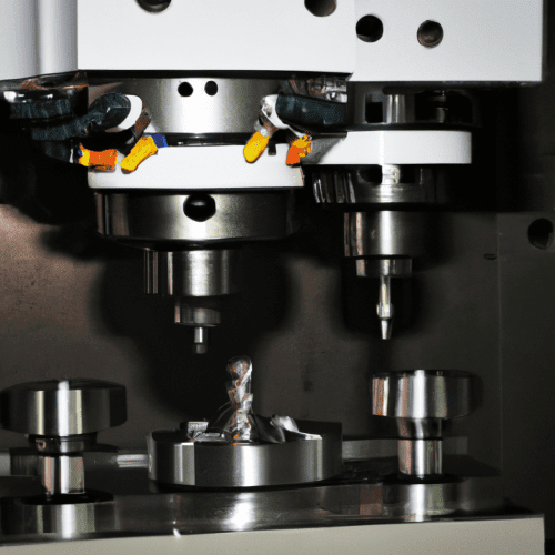
CNC machining offers exceptional accuracy and repeatability, but the achievable precision varies significantly based on numerous factors. Understanding these typical tolerances is essential for engineers and designers to specify realistic requirements, optimize manufacturing costs, and ensure part functionality. Tolerances define the acceptable deviation from a specified dimension, ensuring components fit and perform as intended.
The International Organization for Standardization (ISO) 2768 standard provides general tolerances for linear and angular dimensions on technical drawings where no individual tolerance is explicitly stated. This standard helps streamline communication between designers and manufacturers globally.
Achieving Standard CNC Machining Tolerances
Standard shop tolerances for CNC machined parts typically fall within a range of ±0.005 inches (±0.127 mm). This level of precision is widely achievable on conventional CNC mills and lathes and is suitable for a vast majority of general-purpose components.
For dimensions without specific call-outs, the ISO 2768-1 ‘medium’ (m) tolerance class is often applied as a default. This class strikes an optimal balance between precision and manufacturing cost, making it ideal for generic enclosures, brackets, and non-critical parts.
Achieving these standard tolerances relies on well-maintained machinery, appropriate tooling, and competent programming. Factors like machine rigidity, tool wear, and consistent environmental conditions all contribute to maintaining this level of accuracy.
Precision Milling and Tight Tolerance Control
| Material | Linear CTE (µm/m·°C at ~20°C) |
|---|---|
| Invar 36 | 1.3 |
| Tungsten | 4.5 |
| Titanium Ti-6Al-4V | 8.6 |
| Steel 1018 (mild) | 11.7 |
| Stainless 304 | 17.3 |
| Copper C110 | 16.9 |
| Aluminum (pure) | 23.1 |
| Magnesium | 26 |
| Delrin (POM) | 110 |
When applications demand greater accuracy, precision milling can achieve tighter tolerances, typically around ±0.001 inches (±0.025 mm) or better. This level of precision is considered ‘tight tolerance’ and requires more deliberate process controls.
To consistently hold these tighter dimensions, manufacturers implement rigorous temperature control, consistent tool calibration, and stable workholding setups. Skilled machinists are crucial, often employing optimized toolpaths, controlled feed rates, and multiple finish passes to minimize error.
Material selection also plays a significant role; aluminum alloys like 6061-T6 and 7075-T6 are excellent choices for tight-tolerance work due to their clean machining characteristics and predictable thermal expansion properties. Modern multi-axis CNC machines, including 5-axis systems, enhance precision by reducing the need for multiple setups, thereby improving consistency and accuracy across complex geometries.
Ultra-Precision Machining and Advanced Techniques
For the most demanding applications, ultra-precision machining pushes tolerances to extreme limits, often achieving ±0.0002 inches (±0.005 mm) or even tighter, sometimes reaching sub-micron levels. This domain is critical for industries such as aerospace, medical devices, and optics.
Ultra-precision processes depend on specialized CNC milling and turning equipment with exceptional control, environmental stability, and advanced cutting tools, including diamond-tipped tools. These machines operate in climate-controlled, vibration-optimized rooms to eliminate external influences.
Achieving such minute tolerances often involves techniques beyond traditional milling, such as grinding or Electrical Discharge Machining (EDM). The goal is to produce components with mirror-like surface finishes and dimensional accuracy in the submicron or nanometer domain.
Verifying Accuracy with Coordinate Measuring Machines
Accurate part verification is indispensable for ensuring machined components meet specified tolerances, especially in precision and ultra-precision applications. Coordinate Measuring Machines (CMMs) are paramount metrology tools for this purpose.
CMMs measure physical features of a part by collecting data points across its surface using a probe, then comparing these results against engineering drawings or CAD models. This process verifies dimensional accuracy, geometric tolerances, and complex three-dimensional features with high accuracy and repeatability.
Advanced CMM systems can achieve measurement uncertainties within micrometers, making them essential for quality control in industries requiring micron-level precision. The ‘factor of four’ rule suggests that measurement accuracy should be four times better than the part tolerance being verified.
Mitigating Material Thermal Expansion Factors
Thermal expansion is a critical factor in precision machining, as temperature fluctuations cause materials to change size, directly impacting dimensional accuracy. As a material absorbs heat, its atoms vibrate more vigorously and push further apart, leading to expansion.
Different materials exhibit varying coefficients of thermal expansion (CTE). For instance, aluminum expands approximately twice as much as carbon steel for the same temperature change. This differential expansion must be accounted for to prevent out-of-spec parts or assembly issues.
Machining processes themselves generate heat through friction, creating thermal gradients within the workpiece and cutting tools. Strategies to mitigate this include rigorous environmental control, advanced coolant strategies, and machine features like thermal compensation systems that automatically adjust for temperature variations.
The following table illustrates typical linear thermal expansion coefficients for common engineering materials, highlighting the need for careful material selection and process control in precision machining:
Note: CTE values are approximate and can vary with specific alloy composition, heat treatment, and temperature range.
Optimizing Feeds and Speeds for Tolerance Control
Properly optimized feeds and speeds are fundamental to achieving and maintaining tight tolerances in CNC machining. These parameters directly influence surface finish, tool wear, and the heat generated during cutting.
Spindle speed (RPM) dictates how quickly the tool rotates, while feed rate (IPM or mm/min) determines how fast the tool advances through the material. Balancing these two, along with chip load and depth of cut, is crucial for efficient material removal without compromising precision.
For aluminum, common RPM ranges from 6,000 to 20,000, with feed rates for carbide tooling typically between 0.004 to 0.010 inches per revolution (IPR) for roughing and 0.002 to 0.005 IPR for finishing. For steel, recommended surface speeds for HSS tools are lower, around 60-100 surface feet per minute (SFM) for mild steel, requiring adjustments to RPM and feed rate accordingly.