
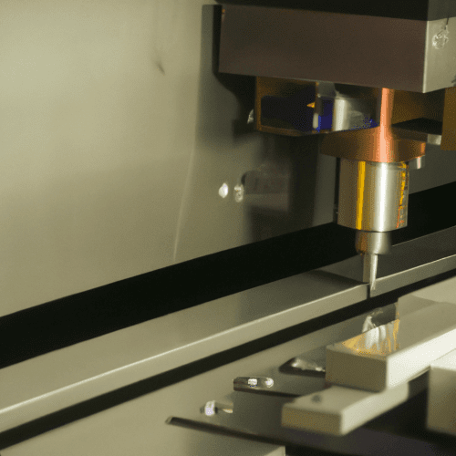
Ensuring the reliable operation of a CNC machine requires meticulous attention to its electronic components. Proper debugging and testing procedures are essential for maintaining precision, preventing costly damage, and ensuring operator safety. A systematic approach to diagnosing electrical issues can significantly extend machine lifespan and optimize performance.
Many common CNC problems, from erratic movements to unexpected shutdowns, originate in the electrical system. Understanding how to identify and rectify these issues is a core skill for any tooling engineer. This guide outlines critical steps for maintaining a robust and responsive CNC electronics setup.
Understanding Stepper Driver Calibration
Stepper motor drivers require precise calibration to deliver optimal torque and prevent overheating. Each stepper motor has a rated current, which should never be exceeded to avoid damage. Setting the current limit too high can cause excessive resonance and vibration, while too low a setting results in insufficient torque and missed steps.
Calibration typically involves adjusting a potentiometer on the driver board to set the reference voltage (Vref), which in turn controls the motor’s current. Before making adjustments, it is crucial to consult the motor’s datasheet for its rated phase current. A common recommendation is to set the trip current (I_trip) to 50% to 60% of the motor’s rated phase current.
To accurately set the current, connect a multimeter to measure the Vref while the driver is powered, but with the motor disconnected. The negative lead of the multimeter should connect to a ground point on the controller board. The positive probe then touches the potentiometer or a designated test point.
Carefully turn the potentiometer with a small, non-conductive screwdriver, observing the voltage reading. Adjust until the calculated Vref value is achieved. After setting, connect the motor and perform test movements, monitoring motor and driver temperatures. Overheating indicates a current setting that is too high, while missed steps suggest it is too low.
Effective Limit Switch Troubleshooting
| Test Type | Frequency | Procedure | Expected Outcome |
|---|---|---|---|
| Visual Inspection | Daily / Before Each Shift | Check for damage, obstruction, cleanliness. | Button is clear, undamaged, and accessible. |
| Functional Test | Monthly | Activate E-stop, verify immediate machine shutdown. | All motion ceases, power to drives removed, manual reset required. |
| Electrical Verification | Annually / After Repair | Multimeter continuity check of NC contacts, wiring integrity. | Contacts show continuity at rest, open when pressed; no wire breaks. |
Limit switches are vital safety components that define the physical boundaries of a CNC machine’s travel, preventing crashes and enabling homing functions. These switches can be mechanical, inductive, or optical, each with specific wiring requirements. Proper installation and configuration are paramount for reliable operation.
Most industrial CNC systems utilize normally closed (NC) limit switches. This configuration is considered fail-safe because a broken wire, loose connection, or switch failure will open the circuit, immediately triggering a stop condition. Conversely, normally open (NO) switches can mask such faults, leading to potential machine damage.
Troubleshooting limit switches often begins with a visual inspection for physical damage, contamination, or loose connections. If a switch plunger sticks or moves slowly, cleaning it may resolve the issue. For electrical verification, use a multimeter in continuity mode to check the switch’s state. An NC switch should show continuity when at rest and open (no continuity) when activated.
If the diagnostic bit on the controller does not change state when a switch is activated, inspect the wiring for breaks or shorts. Shielded cables are highly recommended for limit switch wiring, especially over longer runs, to prevent electromagnetic interference from causing false triggers.
Essential Multimeter Wiring Checks
A multimeter is an indispensable tool for diagnosing electrical issues within a CNC system. It allows for precise measurements of voltage, current, and resistance, helping to pinpoint faulty components or wiring discrepancies. Regular checks can prevent minor issues from escalating into major failures.
Before any multimeter checks, always ensure the machine’s power is disconnected to prevent electrical shock. For continuity tests, set the multimeter to the continuity mode, often indicated by a speaker or musical note symbol. Touch the probes together to confirm the meter beeps, indicating a complete circuit.
To check for continuity in a wire or connection, place the probes on both ends of the segment. A beep confirms a continuous path, while no sound indicates a break. This is particularly useful for verifying ground connections, signal lines, and power supply integrity.
Voltage checks are crucial for verifying power supply outputs and ensuring correct voltage levels reach individual components. Measure DC voltage at various points, such as power supply terminals and driver inputs, comparing readings against manufacturer specifications. Significant deviations can indicate a failing power supply or a wiring issue.
Ensuring Emergency Stop Circuit Integrity
The emergency stop (E-stop) circuit is the most critical safety feature on any CNC machine, designed to immediately halt all motion in hazardous situations. Its design must prioritize fail-safe operation, often bypassing software control to ensure direct hardware intervention.
E-stop buttons typically feature a prominent red mushroom-head design on a yellow background, positioned for easy access. These systems are almost universally wired with normally closed (NC) contacts in a series chain, ensuring that any break in the circuit, including a wire fault, triggers an immediate shutdown.
Regular functional testing of the E-stop circuit is mandatory. Industry best practices recommend daily visual inspections and monthly functional tests. During a functional test, activate each E-stop button and verify that the machine immediately stops all motion and power to hazardous components is removed.
After activation, the E-stop must be manually reset, and the machine should not restart automatically. If any E-stop button feels stiff, fails to latch, or does not operate cleanly, it must be tagged as faulty and repaired immediately. Never operate a CNC machine with a defective E-stop system.
Mitigating Controller Signal Noise
Electrical noise, including electromagnetic interference (EMI) and radio frequency interference (RFI), can severely disrupt CNC controller operations, leading to erratic movements, false triggers, and communication errors. Sources often include variable frequency drives (VFDs), servo motors, and improper cable routing.
Effective noise mitigation strategies are crucial for maintaining system stability. One fundamental practice is single-point grounding, where all system components are bonded to a common earth point, preventing ground loops. Low-resistance earth grounds, typically less than 5 ohms, are essential.
Using shielded cables for signal lines, especially for limit switches and encoders, significantly reduces noise pickup. These shields should be grounded at one end only, typically at the CNC cabinet, to avoid creating ground loops. Twisted pair cables also offer improved noise immunity.
Physical separation of ‘noisy’ power cables from ‘quiet’ signal cables is another key technique. When cables must cross, they should do so at 90-degree angles to minimize inductive coupling. Installing EMI filters on AC power supplies to sensitive components like the motion controller and stepper drivers can also effectively attenuate interference.