
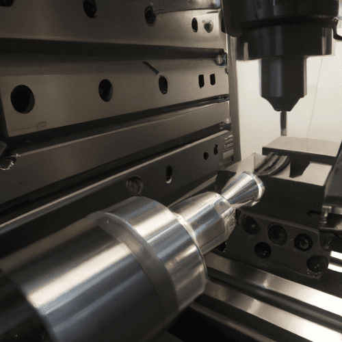
Computer Numerical Control (CNC) machining relies on a precise understanding of various technical terms and concepts. Mastery of these fundamentals is critical for engineers and machinists to achieve optimal part quality, maximize tool life, and ensure efficient machine operation. From programming commands to mechanical tolerances, each element plays a vital role in the overall manufacturing process.
Modern CNC systems integrate sophisticated software and hardware, demanding a comprehensive grasp of underlying principles. This guide explores key terminology that underpins successful CNC operations, providing detailed insights into their function and impact on machining outcomes.
G-Code and M-Code Fundamentals
G-code, often referred to as ‘Geometric code,’ dictates the actual motion and path of a CNC machine’s cutting tool. These commands define where the tool moves, how fast it travels, and the specific path it follows across the workpiece. Examples include linear movements (G01), rapid positioning (G00), and circular interpolation (G02/G03).
M-code, or ‘Miscellaneous code,’ manages auxiliary machine functions that do not involve direct tool movement. These commands control machine actions such as spindle rotation, coolant activation, tool changes, and program stops. Both G-codes and M-codes are essential for a complete CNC program, working in tandem to execute complex machining processes.
A CNC program executes G-code and M-code commands sequentially, with G-codes guiding the tool and M-codes preparing the machine environment. For instance, an M03 command starts the spindle clockwise, while a G01 command then moves the tool for a straight cut. Without M-codes, the spindle would not rotate, coolant would not activate, and tool changes could not occur, rendering G-code instructions ineffective.
Common M-codes are largely standardized across controllers like Fanuc, Haas, and Siemens, though advanced functions may vary by machine builder. Programmers must consult machine documentation to ensure correct M-code usage, as sequencing errors can lead to tool breakage or machine crashes.
Work Coordinate System (WCS) Implementation
| Code Type | Function | Common Examples |
|---|---|---|
| G-code | Controls tool movement and machining paths | G00 (Rapid Traverse), G01 (Linear Interpolation), G02/G03 (Circular Interpolation), G54 (Work Offset) |
| M-code | Manages auxiliary machine functions | M03 (Spindle On Clockwise), M05 (Spindle Stop), M06 (Tool Change), M08 (Coolant On) |
The Work Coordinate System (WCS) establishes a localized coordinate system on the workpiece, simplifying programming and ensuring accurate part positioning. Instead of referencing the machine’s absolute home position, the WCS defines the part’s origin (X0, Y0, Z0) relative to the machine’s capabilities. This allows for easier setup and consistent part production.
G-codes like G54, G55, and G59 are used to select different WCS offsets, enabling multiple parts or features to be machined on a single setup without reprogramming the entire toolpath. Each offset stores the translation values from the machine’s home position to the desired workpiece origin. This flexibility is crucial for efficient production runs.
Setting up the WCS accurately involves touching off the tool to known points on the workpiece or fixture. This process precisely defines the relationship between the tool tip and the part’s zero point. Proper WCS definition is paramount for maintaining dimensional accuracy across all machining operations.
Feeds and Speeds Optimization
Feeds and speeds are critical parameters that directly influence tool life, surface finish, and material removal rates in CNC machining. ‘Feed rate’ refers to how fast the cutting tool moves through the material, typically measured in inches per minute (IPM) or millimeters per minute (mm/min). ‘Spindle speed’ is the rotational speed of the cutting tool, expressed in revolutions per minute (RPM).
Calculating optimal feeds and speeds involves considering several factors: workpiece material, tool material, tool diameter, number of flutes, and desired chip load. Chip load, the thickness of material removed by each cutting edge per revolution, is a fundamental parameter for efficient machining. Modern CAM software often automates these calculations, but understanding the underlying principles remains vital for manual adjustments and troubleshooting.
Advanced CNC controls in 2026 utilize AI-driven optimization to dynamically adjust feeds and speeds based on real-time sensor data, spindle feedback, and predictive tool wear models. This adaptive machining can significantly reduce cycle times and improve surface quality. For instance, some platforms can calculate feed rates dynamically, denoted by ‘F*’ in G-code, based on cutting load and spindle torque signatures.
Backlash Management in CNC Systems
Backlash, also known as ‘lash’ or ‘play,’ is the lost motion in a mechanical system caused by small gaps or clearances between mating components. In CNC machines, backlash typically occurs in drive components such as ball screws, lead screws, gears, and couplings. This results in a momentary delay between the motor’s rotation and the actual movement of the machine axis when the direction of motion reverses.
The presence of backlash can lead to significant positioning errors, dimensional inaccuracies, and poor surface finishes, especially in contouring operations. Common causes include normal wear and tear, loose mounting, incorrect adjustment, poor lubrication, and manufacturing tolerances. Even slight clearance becomes critical in tight-tolerance machining.
Measuring backlash typically involves using a dial indicator. The axis is moved in one direction, then reversed slowly, observing how much the motor turns before the table or tool begins to move. Acceptable backlash values should ideally be minimized, with mechanical fixes preferred for values exceeding 0.005 inches (0.127 mm).
CNC controllers, such as those from FANUC, offer software-based backlash compensation. This technique involves the controller adding an additional amount of movement to the axis when the direction is reversed, effectively accounting for the mechanical play. While software compensation is useful, addressing the mechanical root causes through maintenance and component replacement is often the most effective long-term solution.
Spindle Runout Precision
Spindle runout refers to the deviation of a spindle’s actual rotational axis from its ideal, intended center axis. This ‘wobble’ can occur in the spindle itself, the tool holder, or the cutting tool, leading to inaccuracies in machining. Runout is typically classified into two types: radial runout (perpendicular to the axis) and axial runout (parallel to the axis).
Even minor spindle runout can severely impact machining quality, resulting in reduced dimensional accuracy, poor surface finish, increased vibration, and significantly shortened tool life. For instance, runout causes uneven chip loads, where some cutting edges remove more material than others, leading to premature tool wear and potential breakage.
Measuring spindle runout involves using a precision test bar inserted into the spindle taper and a dial indicator. The Total Indicated Runout (TIR) is measured by slowly rotating the spindle 360 degrees. Acceptable radial runout tolerances vary by machine class and application, but for new precision Vertical Machining Centers (VMCs), values of ≤10μm (0.0004 inches) are expected, with high-speed spindles (HSK) aiming for 2-5μm (0.00008-0.0002 inches).
Causes of excessive spindle runout include worn spindle bearings, contaminated or damaged spindle tapers, improper tool holder seating, and worn or damaged tool holder components. Regular inspection, meticulous cleaning of tapers and tool holders, and minimizing tool stickout are crucial practices to mitigate runout and extend tool life.