
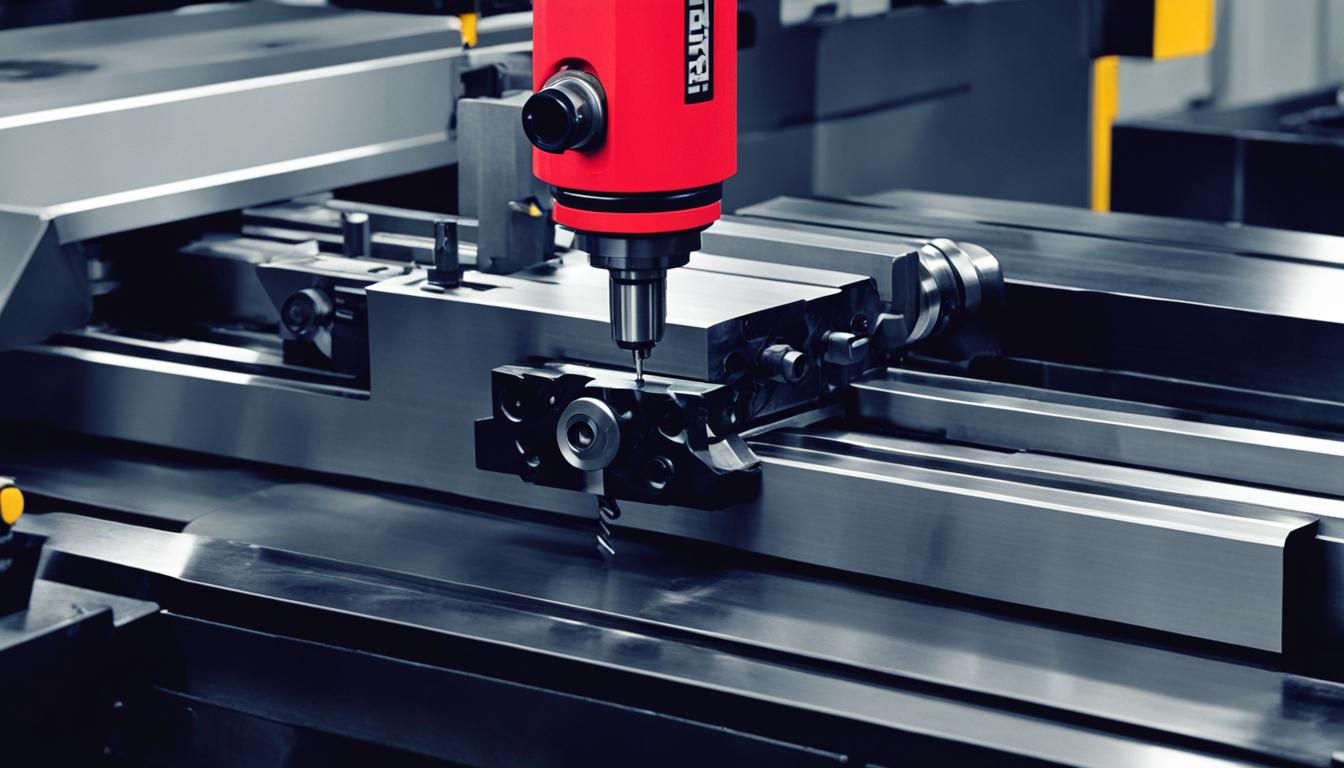
Facing and turning are foundational machining operations performed on a lathe, both involving the removal of material from a rotating workpiece. While often executed on the same machine, their distinct objectives, tool movements, and resulting geometries differentiate them significantly. Understanding these core distinctions is essential for precision manufacturing and effective CNC programming.
Each process plays a critical role in shaping raw stock into finished components, preparing surfaces for subsequent operations, and achieving precise dimensional accuracy. The choice between facing and turning depends entirely on the desired final form and functional requirements of the part.
Facing Operations: Achieving Flatness and Length Control
Facing is a lathe operation specifically designed to create a flat, smooth surface on the end of a rotating workpiece. The primary goal is to machine the end face perpendicular to the workpiece’s axis of rotation, ensuring it is square and suitable for further operations or assembly. This process also precisely controls the overall length of the workpiece by removing material from its end.
During a facing cut, the cutting tool typically moves radially across the workpiece’s end, usually from the outer diameter towards the center. This radial tool movement ensures an even material removal across the entire face. Establishing a clean, flat face is often the initial step in machining a part, providing a crucial datum surface for all subsequent cuts.
Achieving optimal flatness is critical, as deviations can lead to assembly challenges or functional issues in mating components. Factors like material stress, clamping forces, and heat generated during machining can influence flatness, requiring careful process control. Modern CNC facing strategies aim to minimize chatter marks and ensure a smooth, perpendicular surface finish.
Turning Operations: Diameter Reduction and Cylindrical Forms
| Feature | Facing Operation | Turning Operation |
|---|---|---|
| Primary Objective | Surface flattening, length reduction, perpendicularity | Diameter reduction, cylindrical shaping |
| Tool Movement | Radial (perpendicular to axis) | Axial (parallel to axis) |
| Resulting Geometry | Flat, square end face | Cylindrical, conical, or contoured diameters |
| Typical Tolerances | Standard: ±0.05 mm to ±0.1 mm; can be less stable than turning | Standard: ±0.05 mm to ±0.1 mm; Fine: ±0.005 mm to ±0.02 mm |
| Standard Surface Finish (Ra) | Similar to turning, but can degrade near center | 0.8 µm to 1.6 µm (32-63 µin); Fine: 0.4 µm (16 µin) |
| Tool Orientation | Often negative lead angle, cutting edge engages radially | Lead angle and nose radius optimized for longitudinal cuts |
Turning, in its most common form, involves reducing the outer diameter of a rotating workpiece to create cylindrical, conical, or other rotationally symmetric surfaces. This process is fundamental for manufacturing shafts, bushings, and various components requiring precise external or internal diameters.
The cutting tool in a turning operation moves predominantly parallel to the workpiece’s axis of rotation, a movement often referred to as axial or longitudinal feed. This controlled linear motion allows for the gradual removal of material along the length of the part, shaping its profile.
Turning operations are typically divided into roughing and finishing stages. Rough turning rapidly removes excess material, prioritizing high material removal rates over surface finish or tight tolerances. Finish turning, conversely, involves lighter cuts at higher speeds and lower feed rates to achieve the specified dimensional accuracy and desired surface finish.
Tool Movement and Orientation: Axial vs. Radial Dynamics
The fundamental distinction between facing and turning lies in the primary direction of cutting tool movement relative to the workpiece’s axis of rotation. Facing operations are characterized by radial tool movement, where the cutting tool traverses perpendicular to the spindle axis. This motion is typically along the X-axis on a CNC lathe, moving from the workpiece’s circumference towards its center.
Conversely, turning operations primarily utilize axial tool movement, where the cutting tool travels parallel to the spindle axis. This corresponds to movement along the Z-axis on a CNC lathe, reducing the diameter along the length of the part. While both operations occur on a lathe, the orientation of the tool’s feed path dictates the resulting geometry.
Tool holders are designed to facilitate these distinct movements. Axial tool holders align the tool along the spindle axis, suitable for drilling or boring, while radial tool holders position the tool perpendicular to the axis, excelling in external surface machining. The correct selection and orientation of the tool holder are crucial for efficient and precise machining.
Cutting Tool Geometry and Engagement
Cutting tool geometry is specifically optimized for either facing or turning to manage cutting forces, chip evacuation, and surface finish effectively. Facing tools are designed to cut across the end of the workpiece, often featuring a negative lead angle to direct forces towards the chuck and enhance stability. The cutting edge engages the material radially.
Turning tools, on the other hand, are configured for longitudinal material removal. Their geometry, including lead angle and nose radius, influences chip formation and the ability to machine to shoulders or complex profiles. A right-hand turning tool, for instance, removes material when moving from right to left, with its cutting edge on the left side.
The insert shape and entering angle are critical considerations for both. For facing, a square insert with a 75° entering angle (15° lead angle) is often recommended for optimization, redirecting radial forces axially for better stability. Turning tools for external operations might use a 93° entering angle (-3° lead angle) with a D-style (55°) insert for general applications.
Precision, Tolerances, and Surface Finish Considerations
Achieving precise dimensions and a desirable surface finish is paramount in both facing and turning. Standard CNC lathe operations can typically hold tolerances of ±0.05 mm to ±0.1 mm (±0.002 in to ±0.004 in) for general-purpose parts. High-performance CNC lathes, with optimal rigidity and tooling, can achieve tighter tolerances, sometimes reaching ±0.005 mm to ±0.02 mm (±0.0002 in to ±0.0008 in) for critical applications like aerospace components.
Surface finish, measured in Ra (arithmetic average roughness), is also a key quality indicator. Standard turning operations generally yield finishes between Ra 0.8 µm and 1.6 µm (32-63 µin). Precision turning can achieve even finer finishes, down to Ra 0.4 µm (16 µin) or better. Facing operations, particularly near the center of the workpiece where surface speed drops, may require careful parameter adjustment to maintain consistent finish.
Several factors influence both tolerance and surface finish, including cutting speed, feed rate, tool nose radius, tool wear, and the application of coolant. For instance, doubling the feed rate can quadruple roughness, while doubling the tool nose radius can halve it. Proper feeds and speeds are crucial for preventing issues like tool wear, chatter, and poor surface quality.