
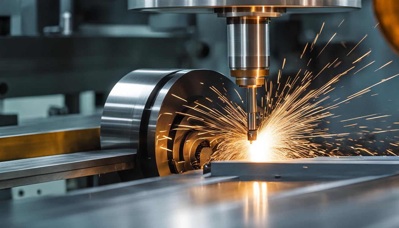
Modern CNC milling operations demand a nuanced understanding of various cutting strategies to achieve optimal part quality, efficiency, and tool life. The selection of a milling approach significantly impacts surface finish, material removal rates, and the ability to produce complex geometries.
Optimizing Surface Finish with Climb Milling
Climb milling, also known as down milling, involves the cutter rotating in the same direction as the workpiece feed. This technique begins with the maximum chip thickness and progressively reduces it, leading to a smoother cutting action. It typically produces superior surface finishes compared to conventional milling.
The decreasing chip thickness at the tool’s exit point minimizes force on the material, reducing tearing and improving surface quality. This method also promotes efficient chip evacuation, as chips are ejected behind the cutter, preventing re-cutting and heat buildup. Reduced tool stress and deflection are additional benefits.
While beneficial for finish, climb milling requires machines with minimal backlash to prevent the cutter from pulling the workpiece into the cut, which could cause chatter or tool breakage. It is generally preferred for finishing passes and when cutting less than half the cutter tool’s diameter. Ductile materials like aluminum and mild steel often benefit from climb milling.
Unlocking Productivity with High-Efficiency Milling
| Material | Operation | Cutting Speed (m/min) | Feed per Tooth (IPT) | Notes |
|---|---|---|---|---|
| 6061 Aluminum | General Milling | 200-500 | 0.002-0.008 | High spindle speed, good chip evacuation. |
| 304 Stainless Steel | Dynamic Milling | 60-180 | 0.002-0.006 | Lower speeds, aggressive feeds, reduced radial engagement. |
| Ti-6Al-4V Titanium | General Milling | 35-70 | 0.004-0.060 (fast-feed) | Low speed, high feed, rigid setup, ample chip space. |
| Engineering Plastics (e.g., Delrin) | General Milling | 150-500 | 0.008-0.012 | High RPM, sharp tools, large rake angles, air blast. |
High-Efficiency Milling (HEM), also known as Dynamic Milling, is a roughing strategy designed to maximize material removal rates and extend tool life. It fundamentally differs from traditional milling by employing a lower radial depth of cut (RDOC) and a significantly higher axial depth of cut (ADOC).
This approach ensures a consistent chip thickness and spreads wear evenly across the entire cutting edge, effectively dissipating heat away from the tool. By maintaining stable cutting conditions, HEM allows for increased feed rates without overloading the cutter, leading to substantial reductions in cycle times. Roughing cycle times can decrease by as much as 80% in specific applications.
Modern CAM software packages now include modules for generating HEM toolpaths, often featuring collision avoidance and optimized toolpath generation. A common starting point for HEM involves a light radial cut, typically 20% or less of the cutter diameter, combined with deep axial engagement.
Precision and Complexity in 5-Axis Continuous Milling
Five-axis continuous milling represents a significant advancement over traditional 3-axis machining, adding two rotary axes to the standard X, Y, and Z. This capability allows for simultaneous movement in five axes, enabling the machining of highly complex geometries in a single setup.
The primary benefits include enhanced precision, improved surface finish, and reduced setup times. Optimal tool orientation can be maintained throughout the toolpath, minimizing deflection, vibration, and heat, which results in tighter tolerances and superior surface quality. Shorter, more rigid tools can be utilized, further reducing chatter and eliminating witness lines.
Industries such as aerospace, medical device manufacturing, and automotive heavily rely on 5-axis CNC milling for components like turbine blades, orthopedic implants, and complex manifolds. Advanced CAM software, including platforms like Mastercam and Fusion 360, is essential for programming complex kinematics, collision detection, and toolpath optimization in 5-axis operations.
Tailoring Cutting Techniques for Diverse Materials
Material properties profoundly influence the selection of cutting tools, geometries, and machining parameters. Factors like hardness, thermal conductivity, and chemical reactivity dictate optimal feeds, speeds, and coolant strategies.
Aluminum alloys, such as 6061, are highly machinable, often benefiting from high spindle speeds and moderate chip loads. Typical cutting speeds for 6061 aluminum range from 200-500 m/min, with chip loads between 0.05-0.15 mm/tooth for carbide end mills. Effective chip evacuation, often with air blast or flood coolant, is crucial to prevent chip packing and welding.
Stainless steels, particularly 304 and 316, present challenges due to their high hardness, toughness, and poor thermal conductivity. Lower cutting speeds (60-180 m/min) and aggressive feed rates (0.05-0.15 mm/tooth) are necessary to prevent work hardening and heat concentration at the tool edge. Dynamic milling techniques with reduced radial engagement (20-30% of cutter diameter) and increased axial depth are recommended.
Machining titanium alloys like Ti-6Al-4V demands a unique approach due to low thermal conductivity, high chemical reactivity, and a tendency to work-harden. Conservative speeds (35-70 m/min for carbide) combined with aggressive feeds are critical to ensure the tool is always cutting, not rubbing, which prevents heat buildup and work hardening. Rigid climb-milling setups, strong cutter teeth, and ample chip space are essential.
Engineering plastics like Delrin, Nylon, and Acrylic require specific tooling and parameters to avoid melting, burr formation, and poor surface finish. Sharp, high-positive rake angle tools (10-20°) with polished flutes and large chip gullets are preferred. High spindle speeds (10,000-24,000 RPM) and moderate feed rates are common, often with air blast for cooling. Single-flute ‘O-flute’ end mills are excellent for chip evacuation.
Strategic Selection of Milling Approaches
Choosing the optimal milling strategy involves evaluating several critical factors beyond just material type. These include the required surface finish, dimensional accuracy, part geometry complexity, production volume, and machine capabilities.
Standard CNC machining tolerances typically range from ±0.05 mm to ±0.13 mm for most milling operations. Achieving tighter tolerances, such as ±0.025 mm or even ±0.013 mm, significantly increases manufacturing costs due to specialized equipment, controlled environments, and longer cycle times. Therefore, tight tolerances should only be specified for critical functional features.
For high-volume roughing, High-Efficiency Milling offers substantial cycle time reductions. When intricate designs and superior surface finishes are paramount, especially on complex 3D contours, 5-axis continuous milling becomes indispensable. For general-purpose finishing, climb milling is often the preferred choice due to its inherent ability to produce smoother surfaces.
Modern engineering practices increasingly integrate AI-driven milling systems for real-time data analysis, predictive tool wear, and automatic optimization of cutting parameters. Digital twin technology also plays a crucial role, simulating tool paths and optimizing feeds and speeds before physical machining, reducing scrap and setup time.