
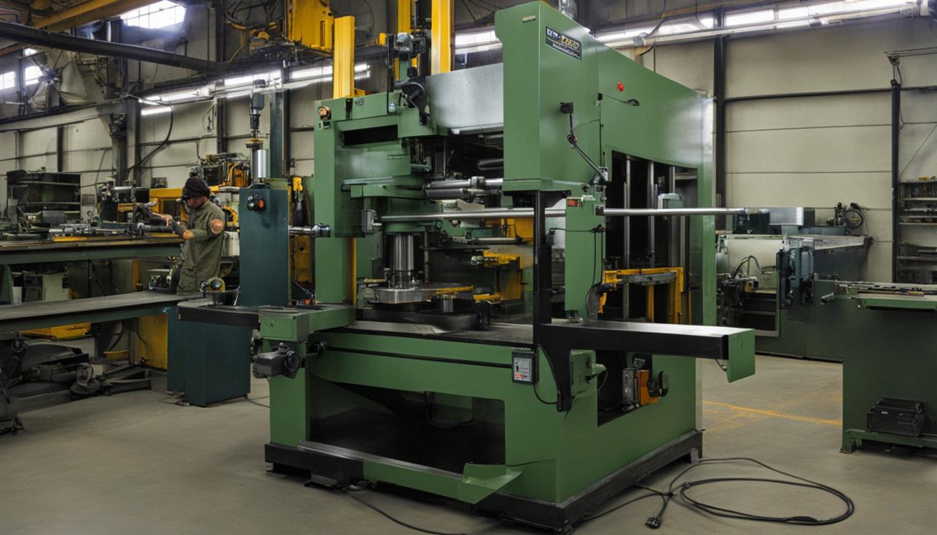
The term ‘center lathe’ precisely describes the fundamental method of workpiece support and rotation employed by this ubiquitous machine tool. Unlike other turning machines that might rely solely on chucks or collets, the center lathe’s defining characteristic is its ability to hold a workpiece between two coaxial points, or ‘centers’, ensuring rotational accuracy and stability during machining operations.
The Core Principle of Center Point Alignment
Machining on a center lathe fundamentally relies on the precise alignment of two opposing points: one originating from the headstock and the other from the tailstock. This setup establishes a singular, stable axis of rotation for the workpiece, which is critical for achieving concentricity and dimensional accuracy in turned components.
Workpieces are typically mounted by engaging conical depressions, often drilled into their ends, with the corresponding centers. This method provides robust support, distributing cutting forces effectively along the workpiece’s length and minimizing deflection, especially for longer shafts or components requiring extensive material removal.
Maintaining coaxial alignment between the headstock and tailstock centers is paramount for precision turning. Any deviation, even slight, can introduce runout, taper, or other geometric errors into the machined part. Modern lathes incorporate highly rigid beds and precise adjustment mechanisms to ensure this critical alignment is maintained throughout the machine’s operational life.
Headstock and Tailstock Centers: the Anchors of Precision
| Parameter | Value Range | Notes |
|---|---|---|
| Cutting Speed (SFM) | 150 – 600 | Depends on steel type, tool material, and depth of cut. |
| Feed Rate (IPR) | 0.002 – 0.015 | Influences surface finish and chip evacuation. |
| Depth of Cut (DOC) | 0.010 – 0.250 inches | Limited by machine rigidity and workpiece stability. |
| Standard Tolerance | ±0.001 – ±0.005 inches | General purpose turning, tighter for precision work. |
The headstock of a center lathe houses the main spindle, which provides the rotational power to the workpiece. A ‘live center’ is typically fitted into the headstock spindle, meaning it rotates with the spindle and the workpiece. This arrangement ensures minimal friction and heat generation at the driving end.
Conversely, the tailstock is a movable component positioned opposite the headstock, providing support at the non-driving end of the workpiece. It can be fitted with either a ‘dead center’ or another ‘live center’. A dead center remains stationary, requiring lubrication between its point and the workpiece’s center hole to prevent galling.
Live centers in the tailstock incorporate internal bearings, allowing the center point to rotate freely with the workpiece, thereby eliminating friction and the need for constant lubrication. This design is particularly advantageous for high-speed machining or when working with heavy workpieces, as it reduces wear on both the center and the workpiece.
Various types of centers exist to accommodate different workpiece geometries and machining requirements. These include standard 60-degree conical centers, half centers for facing operations, pipe centers for tubular work, and bull nose centers for larger diameter bores. Selecting the appropriate center type is essential for secure workholding and optimal machining performance.
A Historical Perspective on Lathe Development
The concept of turning dates back thousands of years, with early lathes being simple bow lathes or pole lathes that used a reciprocating motion to rotate the workpiece. These rudimentary devices laid the groundwork for the continuous rotary motion machines that would follow, gradually improving precision and capability.
The Industrial Revolution brought significant advancements, transforming the lathe from a craft tool into a robust machine capable of mass production. Key innovations included the introduction of the slide rest by Henry Maudslay in the late 18th century, which allowed for precise and consistent tool movement, a critical step towards modern turning.
The term ‘center lathe’ gained prominence as these machines evolved to consistently support workpieces between two fixed or rotating points. This method contrasted with earlier or specialized lathes that might hold work solely in a chuck or on a faceplate. The ‘center’ in its name explicitly highlights this fundamental workholding strategy, distinguishing it from other turning apparatuses.
Workpiece Axis Mounting and Support Mechanics
Mounting a workpiece between centers is a highly effective method for ensuring concentricity and minimizing deflection during turning operations. The workpiece is typically driven by a lathe dog or a drive plate, which transmits the rotational power from the headstock spindle while allowing the tailstock center to provide axial support.
While center mounting is foundational, center lathes are versatile and can also utilize other workholding devices. Three-jaw and four-jaw chucks, collets, and faceplates are commonly employed for shorter workpieces or those that do not require tailstock support. However, even when using a chuck, the machine’s design inherently allows for the use of a tailstock center for added rigidity if needed.
The stability provided by supporting a workpiece at both ends is crucial for maintaining tight tolerances and achieving superior surface finishes. This dual-point support minimizes vibration and chatter, which are common issues in unsupported turning, especially when taking heavy cuts or machining slender components.
For secondary operations, such as machining the internal diameter of a previously turned part, mandrels are often used. These precision shafts are inserted into the workpiece’s bore, and the mandrel itself is then mounted between centers, ensuring that subsequent operations are concentric with the initial turning.
Lathe Design and Operational Mechanics
A center lathe’s robust construction begins with its bed, typically made from cast iron, providing a rigid foundation for all other components. The carriage, which carries the cutting tool, moves along the bedways, allowing for longitudinal feed. The cross-slide and compound rest provide transverse and angular tool movements, respectively.
Power transmission from the main motor to the headstock spindle involves a system of gears or belts, allowing for a range of spindle speeds. The feed mechanism, often driven by a lead screw and feed rod, precisely controls the rate at which the cutting tool advances along or across the workpiece, directly influencing surface finish and material removal rates.
Modern center lathes incorporate advanced features such as hardened and ground bedways, precision ball screws, and sophisticated control systems to enhance accuracy and repeatability. Computer Numerical Control (CNC) center lathes integrate these mechanical principles with digital programming, enabling complex geometries and automated production with exceptional precision.
Achieving optimal machining results requires careful consideration of feeds, speeds, and tool selection. Standard tolerances for turned parts can range from ±0.0005 inches (±0.0127 mm) for general machining to ±0.0001 inches (±0.0025 mm) for high-precision applications, depending on machine capability and material.