
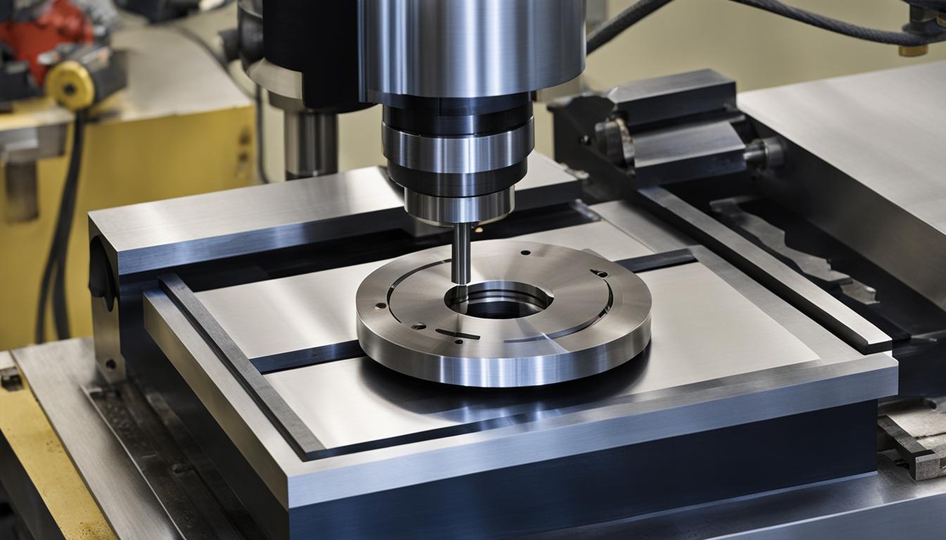
Integrating a 4th axis rotary table significantly expands the capabilities of a standard 3-axis CNC milling machine. This additional axis, typically referred to as the A-axis, introduces rotational movement around the X-axis, allowing the workpiece to be indexed or continuously rotated during machining operations. This upgrade enables the production of more complex geometries and reduces the need for multiple manual setups, directly improving efficiency and part accuracy.
A 4th axis rotary table functions by clamping the workpiece and rotating it in precise, programmable increments. Quality units often achieve resolutions of 0.001° or better. This automated rotation allows the spindle to access multiple faces and features of a part without operator intervention, eliminating potential errors introduced by manual repositioning.
A-Axis or B-Axis Rotational Table Configurations
The designation of a rotary axis as ‘A’ or ‘B’ depends on its orientation relative to the primary linear axes of the milling machine. The A-axis typically rotates around the X-axis, which is the most common configuration for a 4th axis rotary table.
Conversely, a B-axis rotates around the Y-axis. While less common for standalone rotary tables, B-axis rotation is frequently found in 5-axis machining centers, often as part of a trunnion table setup that provides both tilt and rotation. Understanding these distinctions is crucial for proper CAM programming and machine setup, ensuring the correct kinematic chain is applied for the desired part geometry.
Indexing versus Continuous 4th Axis Machining
| Feature | Indexed (3+1) Machining | Continuous 4-Axis Machining |
|---|---|---|
| Rotary Axis Movement | Rotates to fixed position, then locks | Interpolates simultaneously with X, Y, Z |
| Typical Applications | Multi-face features, radial holes, flats | Helical flutes, cam profiles, wrapped contours |
| Setup Rigidity | High (due to mechanical brake) | Moderate (depends on table design) |
| Programming Complexity | Lower | Higher |
| Inter-feature Accuracy | Excellent (single datum reference) | Excellent (simultaneous coordination) |
The operational mode of a 4th axis rotary table falls into two primary categories: indexing (also known as 3+1 machining) and continuous (simultaneous) 4-axis machining. Each mode offers distinct advantages for specific part geometries and production requirements.
Indexed 4-axis machining involves rotating the workpiece to a predetermined angular position, locking it in place with a mechanical brake, and then performing standard 3-axis linear toolpaths (X, Y, Z). This method is highly effective for prismatic components with features distributed across multiple faces, such as radial bolt patterns or keyway flats on a shaft. Locking the rotational axis maximizes setup rigidity, allowing for deeper cuts and higher feed rates without inducing tool chatter.
Continuous 4-axis milling, in contrast, keeps the rotary axis interpolating in real-time, coordinated simultaneously with the X, Y, and Z axes. This is essential for machining geometries that wrap around the part, including cam lobes, helical flutes, and spiral grooves, where the tool path continuously changes in both angle and position. While more complex to program, continuous 4-axis machining enables the creation of intricate contours that are impossible with indexing alone.
Milling Cylindrical Surface Cuts
Milling cylindrical surface cuts is a primary application for 4th axis rotary tables, enabling the creation of features that wrap around a part’s circumference. This capability is crucial for components like shafts with helical grooves, cam profiles, or intricate engravings.
The process involves coordinating the linear movements of the X, Y, and Z axes with the continuous rotation of the A-axis. CAM software plays a vital role in generating the complex toolpaths required to project 2D patterns onto a curved surface, ensuring the cutting tool maintains the correct angular and axial position. This allows for precise detailing on cylindrical objects, often eliminating the need to switch between different machines for turning and milling operations.
Multi-Side Machining Without Manual Flip
A significant advantage of a 4th axis rotary table is its ability to facilitate multi-side machining in a single setup, eliminating the need for manual repositioning of the workpiece. This directly translates to reduced setup times, improved part accuracy, and increased overall efficiency.
By rotating the part to present different faces to the cutting tool, a 4-axis machine can access up to four orthogonal faces and any angular position in between. This single-setup approach maintains a consistent datum reference, which is critical for holding tighter inter-feature tolerances across multiple surfaces. For example, a shaft requiring holes drilled at multiple evenly spaced positions around its circumference can be completed in one setup, saving considerable time compared to a 3-axis machine.
Rotary Workholding Chucks
Effective workholding is paramount for precision 4th axis machining, and rotary workholding chucks are specifically designed for this purpose. These chucks securely grip cylindrical or irregularly shaped workpieces, ensuring stability during rotation and cutting operations.
Common types include 3-jaw and 4-jaw chucks, similar to those used on lathes, but adapted for rotary table integration. Hydraulic or pneumatic actuation provides strong clamping force, which is essential for resisting cutting forces and maintaining positional accuracy. Some advanced rotary tables also feature through-hole bores, allowing for the passage of bar stock or coolant lines, further enhancing versatility.
Modern rotary tables often incorporate features like high-torque motors, precision bearings, and backlash elimination systems to ensure optimal performance. Repeatability, often measured to ISO 230-2 standards, is a critical specification, with high-precision units achieving ±2 arc-seconds or better. This ensures consistent results, especially in high-volume production environments where tight tolerances are non-negotiable.
Standard Tolerances and Feeds & Speeds
Achieving precise results with a 4th axis requires adherence to established tolerances and optimized feeds and speeds. Standard CNC machining tolerances typically range from ±0.005 inches (0.127 mm) for most linear dimensions, with precision applications reaching ±0.001 inches (0.025 mm) or even tighter for reamed holes.
Rotary table accuracy, specifically indexing accuracy and repeatability, is measured in arc-seconds. High-precision rotary tables can achieve positional accuracies of ±0.5 arc-seconds (±0.00014°) and repeatability as fine as ±4 arc seconds. These tight tolerances are critical for industries like aerospace and medical devices.
Feeds and speeds for 4th axis milling are highly dependent on the material, tool type, and desired surface finish. For aluminum alloys like 6061, typical carbide end mill cutting speeds range from 600-1500+ SFM, with RPMs often between 6,000 and 20,000. Feed rates for aluminum can be around 40-80 IPM.
- For 304 stainless steel, carbide end mills typically use cutting speeds of 200–250 SFM (60–75 m/min).
- Feed per tooth for 304 stainless steel is commonly between 0.002–0.006 in/tooth (0.05–0.15 mm/tooth), resulting in feed rates of 15–30 IPM for a standard 1/2″ end mill with four flutes.
- These parameters are starting points; adjustments are necessary based on tool diameter, flute count, tool engagement, machine rigidity, and coolant delivery.