
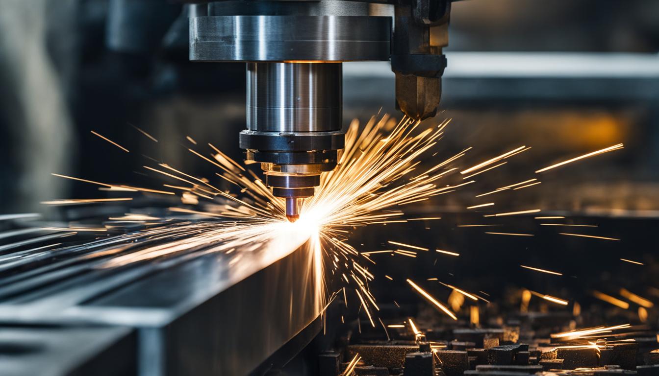
Computer Numerical Control (CNC) metal milling is a subtractive manufacturing process that precisely shapes metal workpieces by removing material with rotating cutting tools. This highly automated method ensures exceptional accuracy and repeatability, making it indispensable across various industries. Modern CNC machines integrate advanced software with robust hardware, enabling the production of intricate components with minimal human intervention.
The core principle involves a programmed sequence of tool movements, guided by G-code, to achieve the desired part geometry. This digital control minimizes human error and significantly enhances product quality. From aerospace to medical device manufacturing, CNC milling is crucial for creating parts with strict tolerance levels.
Subtractive Part Profiling Principles
Subtractive manufacturing defines processes that form parts by removing material from a solid block, billet, or sheet. This method contrasts with additive manufacturing, which builds objects layer by layer. CNC milling, turning, drilling, and grinding are common subtractive techniques used to achieve precise forms.
The process begins with a Computer-Aided Design (CAD) model, which is then translated into Computer-Aided Manufacturing (CAM) toolpaths. These toolpaths generate the G-code that directs the CNC machine’s movements. This digital workflow ensures high accuracy and repeatability, critical for mass production of precision components.
Subtractive profiling is essential for creating complex geometries, undercuts, and intricate features that would be challenging to produce manually. The ability to precisely remove material ensures that components fit into assemblies without gaps, enhancing product reliability and safety.
Multi-Axis Cutter Toolpaths
| Material | SFM Range | Typical Chip Load (per tooth) | Standard Tolerance |
|---|---|---|---|
| Aluminum (6061) | 800 – 1,000 | 0.003″ – 0.008″ | ±0.005″ (±0.127 mm) |
| Alloy Steel (4140, Annealed) | 250 – 400 | 0.0015″ – 0.003″ | ±0.005″ (±0.127 mm) |
| Titanium (Ti-6Al-4V) | 100 – 180 | 0.001″ – 0.002″ | ±0.005″ (±0.127 mm) |
Multi-axis CNC machining significantly enhances manufacturing capabilities by allowing the cutting tool and workpiece to move simultaneously across more than three axes. While 3-axis machines move along X, Y, and Z, 4-axis machines add one rotational axis, and 5-axis machines incorporate two rotational axes. This expanded movement enables the creation of intricate shapes, contours, and undercuts that are impossible with traditional 3-axis methods.
A key advantage of multi-axis machining is the ability to complete complex jobs in a single setup, eliminating the need for multiple repositioning operations. This consolidation reduces setup time, shortens cycle times, and improves overall production efficiency. Optimized toolpaths maintain an ideal angle of contact with the workpiece, minimizing tool wear and distributing cutting forces more evenly.
Multi-axis systems also contribute to superior surface finishes by reducing tool marks and surface imperfections. The continuous, smoother cutting paths minimize vibrations, often reducing or eliminating the need for secondary finishing operations like sanding or polishing. This capability is vital for industries requiring high-performance parts, such as aerospace and medical device manufacturing.
High-Speed Spindle Rotation Dynamics
High-speed machining (HSM) utilizes spindle speeds far exceeding conventional limits, often ranging from 40,000 to 90,000 RPM. This approach dramatically reduces cycle times and enhances precision, making it crucial for industries demanding both efficiency and accuracy. HSM is particularly beneficial for aerospace-grade aluminum, titanium, and medical components, where surface quality is paramount.
Operating at high surface feet per minute (SFM) with lighter, layered cuts minimizes vibration and heat buildup, resulting in smoother, more consistent finishes. High RPMs are essential for small diameter tools to achieve optimal surface cutting speeds. However, selecting the right spindle involves balancing speed, torque, and power, as faster RPM does not always equate to better performance for all materials and tooling.
Modern high-speed spindles are engineered with advanced bearing systems and lubrication methods to sustain extreme rotational speeds. While 30,000 RPM is common, some spindles can exceed 100,000 RPM, with bearing diameter being a primary limiting factor. Proper maintenance and avoiding overload are critical for extending spindle life, which typically averages around 6,000 hours before a rebuild is required.
Metal Feed Rate Calculations
Accurate feed rate calculations are fundamental to efficient CNC metal milling, directly impacting tool life, surface finish, and material removal rates. The primary parameters involved are Surface Feet per Minute (SFM), Revolutions Per Minute (RPM), and chip load per tooth (IPT or CPT). SFM defines the linear velocity at the cutting edge, while RPM is the rotational speed of the spindle.
The formula for calculating RPM from SFM is: RPM = (SFM × 3.82) ÷ Cutter Diameter (inches). Once RPM is determined, the feed rate in Inches Per Minute (IPM) is calculated using: IPM = RPM × Number of Flutes × Chip Load per Tooth. This ensures each tooth removes a consistent chip, preventing rubbing or excessive cutting forces.
Chip load is a critical factor; for 6061 aluminum, it typically ranges from 0.002′ for finishing to 0.015′ for roughing with larger tools. Insufficient chip load can cause rubbing and work hardening, while excessive chip load leads to premature tool wear or breakage. Material hardness, tool material (HSS vs. carbide), and machine rigidity all influence optimal feed and speed parameters.
Flood Coolant Chip Evacuation
Effective chip evacuation is paramount in CNC metal milling to prevent chip recutting, reduce heat buildup, and extend tool life. The accumulation of metal chips in the cutting zone can lead to surface damage, dimensional inaccuracies, and premature tool wear. Modern manufacturing demands optimized chip evacuation, especially for complex geometries and difficult-to-cut materials like titanium and hardened steels.
Flood coolant systems are a primary method for chip removal, providing hydraulic flushing, chip breaking, and boundary lubrication. High-velocity fluid pushes chips away from the tool tip, while the fluid jet can impact and fracture chip formations. This lubrication also reduces friction between the chip and the tool’s rake face, lowering heat and adhesion.
While standard flood coolant at 4–6 bar provides basic flushing, high-pressure coolant (HPC) systems, operating at 70–200 bar, significantly enhance chip evacuation. HPC systems are particularly effective in deep drilling and high-performance machining, breaking long chips into smaller, more manageable segments. Proper nozzle alignment and sufficient pressure are crucial to direct coolant flow precisely into the cutting zone, even with lower-pressure systems.