
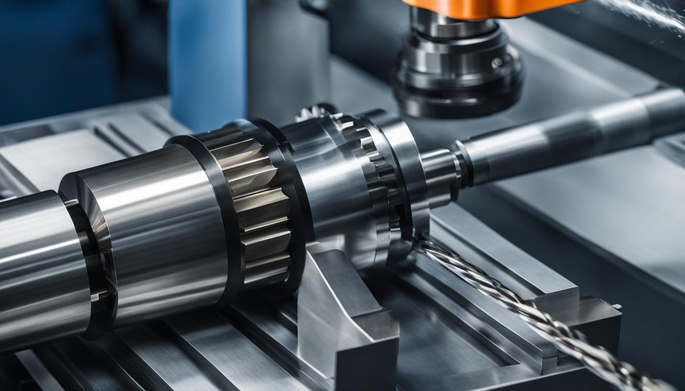
Computer Numerical Control (CNC) turning is a subtractive manufacturing process that precisely shapes cylindrical workpieces. This method involves rotating a material blank at high speeds while a stationary cutting tool removes material to achieve the desired geometry. The entire operation is governed by a computer program, ensuring high accuracy and repeatability across production runs.
CNC turning is fundamental for creating parts with rotational symmetry, such as shafts, pins, bushings, and threaded components. Unlike milling, where the tool rotates and the part remains static, in turning, the workpiece spins, and the cutting tool moves linearly. This distinction is crucial for understanding the process dynamics and achievable part features.
The Foundation: Workpiece Rotation and Clamping
Workpiece rotation is the core principle of CNC turning, where the material is securely held and spun by a chuck or collet. The chuck, a mechanical clamping device mounted on the machine’s spindle, ensures the workpiece remains stable and accurately centered during machining.
Various chuck types are employed, with the three-jaw self-centering chuck being the most common for general turning operations due to its ease of use and ability to center round or hexagonal workpieces automatically. Power chucks, often hydraulic or pneumatic, offer higher gripping force and faster clamping/unclamping, making them ideal for high-volume production.
Collet chucks, another type of work-holding device, use a tapered sleeve to grip the workpiece snugly, providing excellent grip strength and precision for small, delicate, or high-tolerance parts. Proper workholding is paramount; a stable setup directly influences surface finish, geometric accuracy, and even tool life.
Precision Tool Movement and Axis Control
| Parameter | Typical Range (Turning) | Notes |
|---|---|---|
| Standard Diameter Tolerance | ±0.005″ (±0.13 mm) | Achievable with common tooling and setups. |
| Precision Diameter Tolerance | ±0.001″ to ±0.002″ (±0.025 mm to ±0.05 mm) | Requires optimized tooling, rigid workholding, and controlled environment. |
| Surface Roughness (Ra) – Standard Turning | 0.8–1.6 µm | Achieved with typical CNC turning operations. |
| Surface Roughness (Ra) – Precision Turning | 0.4 µm or better | Requires slower finishing passes and optimized parameters. |
| Aluminum 6061 Cutting Speed (SFM) | 600-1200 SFM (carbide tooling) | Promotes good chip breaking and evacuation. |
| Aluminum Roughing Feed Rate (IPR) | 0.004-0.010 IPR | For carbide tooling. |
| Aluminum Finishing Feed Rate (IPR) | 0.002-0.005 IPR | For finer surface finish. |
| Steel 1018 Cutting Speed (SFM) | 300-400 SFM | Typical starting SFM for carbide. |
| Stainless Steel 304 Cutting Speed (SFM) | 200-300 SFM | Typical starting SFM for carbide. |
CNC lathes typically operate with at least two linear axes: the X-axis and the Z-axis. The Z-axis controls the longitudinal movement of the cutting tool, parallel to the lathe spindle axis, with the positive direction moving away from the chuck towards the tailstock.
The X-axis governs the transverse motion of the cutting tool, perpendicular to the spindle axis, controlling the diameter of the workpiece. These axes are driven by servo motors and precision ball screws, allowing for highly accurate and repeatable tool positioning as dictated by the CNC program.
The cutting tool itself is mounted on a stationary tool post, which is engineered for rigidity and quick tool changes. Modern tool posts often feature quick-release mechanisms, enabling efficient swapping of various cutting tools required for different operations, from roughing to finishing.
Outer Diameter Turning Passes: Shaping External Features
Outer diameter (OD) turning involves removing material from the external surface of a rotating workpiece to achieve a specified diameter and profile. This process typically begins with roughing passes, which prioritize high material removal rates.
Roughing passes utilize higher feed rates and greater depths of cut to quickly bring the part close to its net shape. Following roughing, finishing passes are executed at slower feed rates and shallower depths of cut to achieve the final dimensions and desired surface finish.
Achievable tolerances in CNC turning vary, with standard commercial tolerances typically around ±0.005 inches (±0.13 mm) on general diameter features. Precision tolerances of ±0.002 inches (±0.05 mm) are attainable for critical diameters, requiring optimized tooling, rigid workholding, and controlled environments.
Surface finish, measured in Ra (arithmetic average roughness), is significantly influenced by feed rate, cutting speed, and tool nose radius. Standard turning operations typically yield Ra values between 0.8–1.6 µm, while precision turning can achieve 0.4 µm or better.
Inner Diameter Boring: Creating Internal Geometries
Boring is a secondary turning operation used to enlarge, refine, and improve the accuracy of an existing hole. This process employs a single-point cutting tool, known as a boring bar, to remove material from the internal diameter of a workpiece.
Selecting the correct boring bar is critical, considering factors like material, hole diameter, and depth of cut. Solid carbide boring bars offer maximum stiffness for smaller diameters, while damped bars are essential for deep bores to mitigate chatter and improve surface finish.
Rigidity is paramount in boring; maintaining a short overhang, ideally less than or equal to three times the bar diameter, is crucial for stable operation. Increasing the bar diameter significantly enhances stiffness, as stiffness grows with the diameter to the fourth power.
General CNC boring can achieve typical accuracies of ±0.01–0.05 mm, with high-end machines reaching ±0.001–0.005 mm under optimal conditions. Boring is chosen when diameter tolerance is tight, roundness is critical, or the hole axis must align precisely with other features.
Automatic Thread Cutting: Precision Fastener Creation
Automatic thread cutting on a CNC lathe involves generating precise helical grooves on internal or external cylindrical surfaces. This operation is typically performed using specialized G-code canned cycles, such as G76 or G92, which simplify programming complex threading paths.
The G76 cycle is a single-block command that automates multiple threading passes, including automatic in-feed and compound cutting, significantly streamlining the process. Key parameters for G76 include the minor diameter (X), thread end point (Z), thread depth (K), first pass depth (D), and thread pitch (F).
Thread cutting requires careful consideration of spindle speed to prevent issues like ‘messy buckle threads’ due to servo system delays, with an empirical guideline suggesting spindle speed (n) should be less than or equal to 1200 divided by the pitch (P) minus 80. Appropriate lead-in and lead-out lengths are also necessary to ensure clean thread engagement and disengagement.
The depth of cut for each pass in thread cutting typically decreases as the thread progresses, reducing chip load and improving finish. A final ‘spring pass’ without additional in-feed is often performed to ensure the thread reaches its programmed depth and to improve surface quality.