
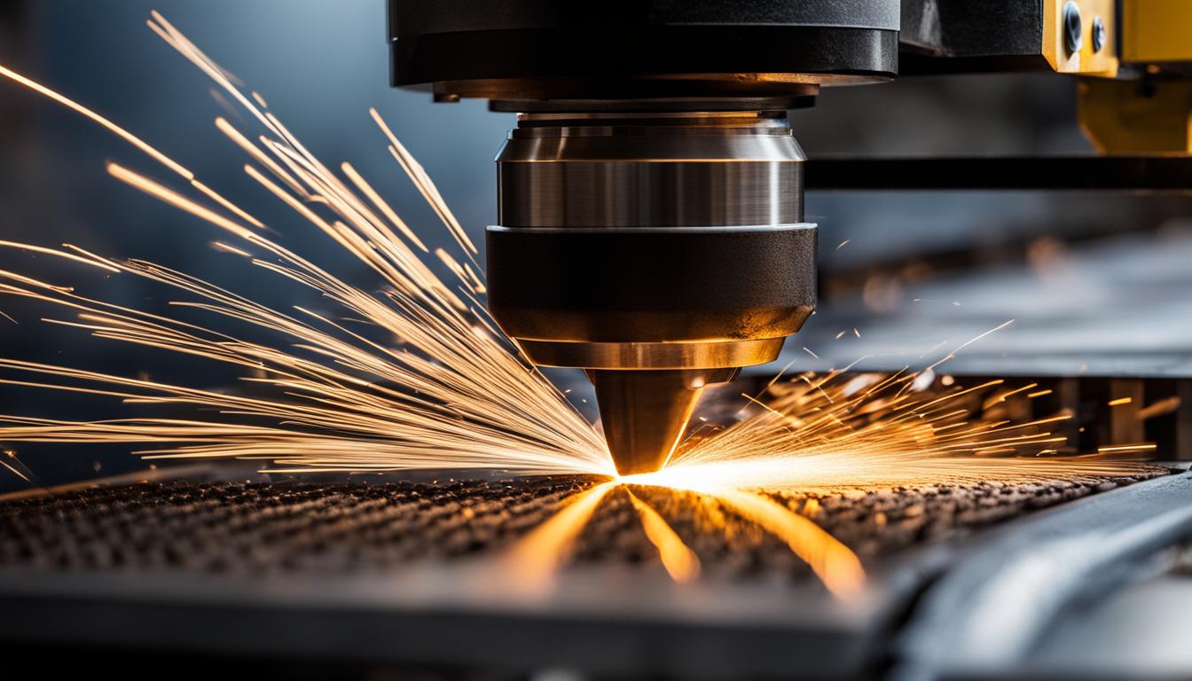
Laser cutting is a highly precise thermal process that utilizes a focused, high-power laser beam to melt, burn, or vaporize material along a programmed path. This advanced manufacturing technique is widely employed across industries such as automotive, aerospace, electronics, and medical manufacturing for cutting various materials, including metals, plastics, ceramics, wood, and fabrics.
The core principle involves concentrating intense light energy onto a localized area of the workpiece, generating significant heat. A computer numerical control (CNC) system directs the laser, ensuring accurate and repeatable cuts.
Focused Laser Beam Thermal Energy
Laser cutting initiates when a highly concentrated laser beam strikes the material’s surface, causing rapid heating. The material absorbs this energy, leading to a localized temperature increase that can reach melting or vaporization points.
Metals with high reflectivity, such as aluminum, initially resist absorption, while darker or coated materials absorb energy more efficiently. Once absorbed, the intense energy creates a steep thermal gradient, where the immediate cutting zone reaches extreme temperatures.
This thermal interaction results in material removal through several mechanisms, including melting, vaporization, and chemical degradation. The surrounding material, exposed to elevated heat without fully melting, forms a ‘heat-affected zone’ (HAZ), where microstructural changes can occur, potentially impacting mechanical properties like hardness and strength.
Assist Gas Molten Metal Blowing
| Feature | Fiber Laser | CO2 Laser |
|---|---|---|
| Wavelength | ~1.064 µm | ~10.6 µm |
| Best For | Sheet metal, reflective metals (aluminum, copper) | Thick plate, wood, acrylic, textiles |
| Speed (thin gauge) | 3–5x faster than CO2 (under 5mm) | Slower on thin material |
| Energy Efficiency | 40–50% wall plug | 5–10% wall plug |
| Beam Delivery | Flexible fiber optic cable | Mirrors and lenses (free-space) |
| Maintenance | Minimal, sealed fiber | Higher (mirror alignment, tube replacement) |
Assist gases are critical components in the laser cutting process, serving multiple functions beyond simply expelling molten material. They significantly influence cut quality, speed, and overall efficiency.
The primary role of the assist gas is to blow away the molten or vaporized material from the kerf, preventing it from re-solidifying on the cut surface and ensuring a clean, precise edge. This also protects the laser”s focusing lens from debris.
Oxygen, nitrogen, and compressed air are the most common assist gases. Oxygen is frequently used for cutting carbon and mild steel, as it reacts exothermically with the metal, generating additional heat that accelerates the cutting process. This allows for faster cutting speeds, especially on thicker materials.
Nitrogen, an inert gas, does not react with the material. Instead, it acts as a high-pressure jet to remove molten metal, creating clean, oxide-free edges. This is particularly beneficial for stainless steel, aluminum, and parts requiring subsequent welding or painting, as it eliminates the need for extensive post-processing.
CNC Gantry Motion Control
Computer Numerical Control (CNC) systems are fundamental to laser cutting, providing the precise motion control necessary for intricate and accurate part fabrication. The CNC interprets digital design files (CAD/CAM) and translates them into machine movements.
Gantry systems are a common architecture in laser cutters, where the cutting head moves along X, Y, and sometimes Z axes. These systems often employ servo motors and high-resolution linear encoders to achieve the required speed and positional accuracy. Flying optics systems, where the workpiece remains stationary and the laser head moves, are prevalent for large sheet processing.
The precision of CNC motion control directly impacts the dimensional accuracy and repeatability of laser-cut parts. Modern systems can achieve impressive tolerances, often within ±0.005 inches (±0.127 mm) for general applications, with advanced fiber laser systems capable of ±0.0005 inches (±0.0127 mm) for critical features under optimal conditions.
Fiber vs CO2 Laser Optics
The choice between fiber and CO2 laser technologies significantly impacts material compatibility, cutting speed, and operational costs. Both types utilize different lasing mediums and wavelengths, leading to distinct performance characteristics.
CO2 lasers generate a beam by electrically exciting a gas mixture, typically producing a longer wavelength of 10.6 micrometers (µm). This wavelength is well-suited for a wide range of materials, including wood, acrylic, plastics, and thicker metals. CO2 systems traditionally use a series of mirrors and lenses for beam delivery.
Fiber lasers, conversely, generate light within a solid optical fiber doped with rare-earth elements, emitting a much shorter wavelength, typically around 1.064 µm. This shorter wavelength is absorbed more efficiently by metals, making fiber lasers exceptionally fast and efficient for cutting thin to medium-gauge metals, including highly reflective materials like aluminum and brass.
Fiber laser beam delivery typically involves flexible fiber optic cables, which offer greater flexibility and reduced maintenance compared to the articulated mirror systems of CO2 lasers.
Kerf Width Characteristics
Kerf refers to the width of material removed by the laser beam as it cuts through a workpiece. It is a critical parameter that directly affects the dimensional accuracy of finished parts, nesting efficiency, and the cumulative tolerance stack in multi-part assemblies.
Kerf width is not a fixed property and is influenced by numerous factors, including the laser type (CO2 vs. fiber), laser power, cutting speed, material type, material thickness, focal length of the lens, and assist gas pressure.
Typical laser cutting kerf widths generally range from 0.08 mm to 1 mm. Fiber lasers often produce a tighter kerf, typically between 0.10 mm and 0.5 mm, especially on thin sheet metals. CO2 lasers tend to have kerf widths in the 0.25 mm to 0.5 mm range.
Kerf is rarely a perfectly parallel-sided slot; it often exhibits a slight taper, usually wider at the top surface where the beam enters and narrower at the bottom. This taper can be 0.02–0.05 mm on thin sheet and more pronounced on thicker plates. Modern CAM software typically compensates for kerf by offsetting the tool path, ensuring parts meet specified dimensions.