
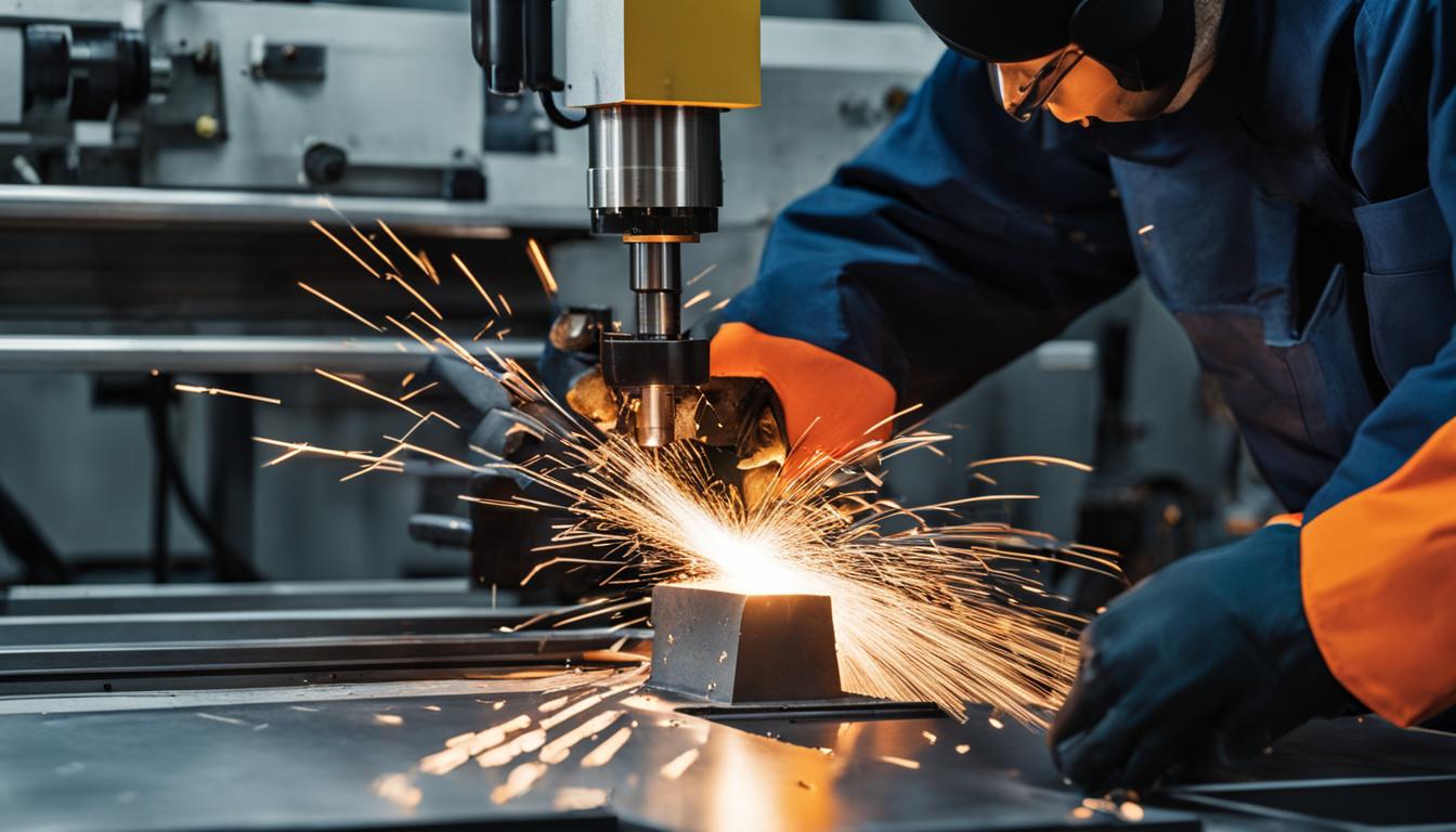
Operating a Computer Numerical Control (CNC) machine demands a blend of technical proficiency and meticulous attention to detail. Modern manufacturing relies heavily on CNC technology for precision and efficiency, making skilled operators indispensable. This guide outlines essential practices for optimal machine performance and safety.
Establishing Safe Machine Operation
Prioritizing safety is paramount in any CNC machining environment. Before initiating any operation, a thorough pre-operational safety check must be completed. This includes inspecting machine components for loose bolts, worn belts, or damaged cables, and verifying that lubrication systems are functioning correctly.
The work area surrounding the machine must be clear of unnecessary objects, with adequate lighting and ventilation. Operators should confirm that the workpiece is securely fastened to prevent movement during machining and that the correct cutting tool is installed and in good condition.
All machine guards and enclosures must be in place, and emergency stop buttons should be tested to ensure immediate functionality. Personal Protective Equipment (PPE) is non-negotiable; safety glasses with side shields, hearing protection, and steel-toe boots are minimum requirements. Cut-resistant gloves are essential for handling sharp materials, but never when operating rotating tools.
Efficient G-Code Program Management
| Material Type | Typical Tolerance (mm) | Notes |
|---|---|---|
| Aluminum Alloys | ±0.05 | Excellent machinability |
| Steel Alloys | ±0.08 | Good dimensional stability |
| Stainless Steel | ±0.10 | More difficult to machine |
| Brass/Copper | ±0.05 | Good machinability |
| Engineering Plastics | ±0.15 to ±0.25 | Thermal sensitivity, flexibility |
| Titanium Alloys | ±0.13 | Difficult to machine |
Loading G-code programs accurately is a critical step in the CNC workflow. Programs are typically transferred to the machine control via USB, network connections, or DNC (Distributed Numerical Control) systems. Modern DNC software often integrates with machine monitoring and tool life management systems.
Before execution, verifying the G-code program is crucial to prevent costly errors and potential machine damage. Simulation software, such as Vericut Verification, NCPlot v2, CIMCO Edit, or browser-based tools like CutViewer and NC Viewer, can accurately emulate G-code and control logic. These tools detect potential collisions, verify toolpaths, and confirm feeds and speeds before actual machining begins.
Many advanced simulators support Fanuc Macro B syntax, allowing for the verification of complex parametric programs, subroutines, and variable calls. This level of pre-validation significantly reduces setup time and enhances overall process reliability.
Accurate Workpiece Measurement Techniques
Measuring workpiece dimensions precisely is fundamental to achieving specified tolerances and ensuring part quality. Standard CNC machining tolerances typically range from ±0.05 mm to ±0.13 mm for most milling and turning operations. Tighter tolerances, such as ±0.01 mm, are achievable in high-precision milling under controlled conditions but significantly increase costs.
Operators utilize various metrology tools, including calipers, micrometers, and height gauges, for post-process inspection. In-process measurement techniques, such as on-machine probing, are increasingly common. Probes can measure geometric features, update tool offsets, and verify part dimensions without removing the workpiece from the machine, improving efficiency and accuracy.
Material properties directly influence achievable tolerances; metals generally allow tighter tolerances than plastics due to better dimensional stability. For instance, aluminum alloys can achieve ±0.05 mm, while engineering plastics often require wider tolerances of ±0.15 mm to ±0.25 mm.
Proactive Tool Wear Monitoring
Monitoring tool wear is essential for maintaining machining quality, efficiency, and tool life. Wear is inevitable due to friction and contact between the tool and workpiece, leading to issues like dull cutting edges, poor surface finish, and dimensional inaccuracies.
Traditional methods include visual inspection, tactile inspection, and monitoring changes in cutting sound or vibration. Modern CNC machines increasingly integrate automated monitoring systems using sensors and machine vision. These systems track tool wear in real-time, providing feedback for adjustments or automatic tool replacement.
Advanced techniques involve spindle load monitoring, acoustic emission analysis, and vibration detection. An increase in spindle load, abnormal sounds, or shifts in vibration patterns can signal tool wear. AI-powered systems analyze these data streams to predict tool degradation and optimize tool life management.
Tool life management systems, often implemented through CNC macros or dedicated software, track tool usage and can automatically switch to sister tools when wear thresholds are met. This proactive approach minimizes unplanned downtime and ensures consistent part quality.
Optimizing Machining Through Feed Overrides
Adjusting feed overrides allows operators to fine-tune machining parameters in real-time, responding to dynamic cutting conditions. Feed rate, measured in units per minute or per revolution, dictates how fast the cutter moves through the material, directly impacting chip thickness, surface finish, and tool life.
Spindle speed, or RPM, controls the rotational speed of the cutting tool, influencing tool wear and energy consumption. Operators must balance these parameters based on workpiece material, tool material, and desired surface finish. Harder materials generally require slower cutting speeds to prevent excessive tool wear.
Feed rate optimization features in CAM software allow for automatic reduction of feed rates before corners and acceleration afterward, minimizing torque loads and improving part quality. Manual adjustments via feed override knobs on the machine control enable operators to react to unexpected conditions like chatter or excessive heat.
Careful observation of chip formation, cutting sound, and surface finish during a test cut provides valuable feedback for override adjustments. Straw or blue chips indicate excessive heat, while long, snarled chips suggest chip evacuation issues, prompting adjustments to feed or speed.