
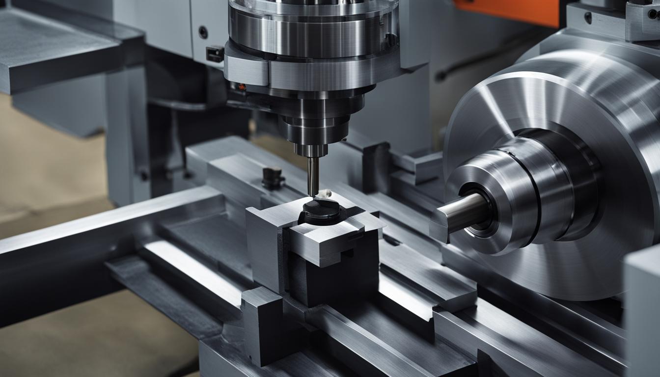
Computer Numerical Control (CNC) machining encompasses a broad range of subtractive manufacturing processes, each optimized for specific part geometries and production requirements. While both CNC lathes and CNC mills are foundational machine tools, their operational principles and primary applications diverge significantly.
Understanding these core distinctions is essential for engineers and machinists to select the appropriate equipment for a given task, ensuring efficiency, precision, and cost-effectiveness in manufacturing operations.
Rotating Workpiece versus Rotating Cutter
The most fundamental difference between a CNC lathe and a CNC mill lies in which component rotates during the cutting process. A CNC lathe, or turning machine, holds the workpiece in a chuck or collet, rotating it at high speeds around a central axis. Stationary cutting tools then engage the spinning material to remove chips and form the desired geometry.
Conversely, a CNC mill, or machining center, secures the workpiece in a fixed position on a table. The cutting tool itself, typically an end mill, drill, or tap, is mounted in a rotating spindle. This rotating tool then moves along multiple axes to remove material from the stationary workpiece, creating complex features and shapes.
Cylindrical versus Flat and 3D Geometry
| Feature | CNC Lathe (Turning Center) | CNC Mill (Machining Center) |
|---|---|---|
| Primary Motion | Workpiece rotates, tool is stationary (or rotates for live tooling) | Cutter rotates, workpiece is stationary |
| Typical Axes | 2-axis (X, Z) standard; 3-axis (X, Z, C), 4-axis (X, Z, C, Y), 5-axis (X, Z, C, Y, B) with live tooling | 3-axis (X, Y, Z) standard; 4-axis (X, Y, Z, A/B), 5-axis (X, Y, Z, A/B, C) |
| Common Part Geometry | Cylindrical, conical, spherical, shafts, bushings, rings, threaded components | Prismatic, blocks, plates, housings, brackets, complex 3D contours, molds |
| Primary Operations | Turning, facing, boring, drilling (on-center), threading, grooving, parting | Milling, drilling, tapping, reaming, contouring, pocketing, surfacing |
| Advanced Capabilities | Live tooling for off-center milling/drilling, Y-axis for complex turned features | Multi-axis for complex geometries, undercuts, single-setup completion |
| Standard Tolerances | ±0.005 in (±0.127 mm) for most metals; precision to ±0.001 in (±0.025 mm) | ±0.005 in (±0.127 mm) for most metals; precision to ±0.001 in (±0.025 mm) |
CNC lathes are inherently designed for producing parts with rotational symmetry. Their primary function is to create cylindrical, conical, or spherical components such as shafts, pins, bushings, and flanges. Operations like turning diameters, facing ends, grooving, and threading are standard on these machines.
CNC mills, on the other hand, excel at machining prismatic parts and complex three-dimensional surfaces. They are ideal for creating features like flat surfaces, pockets, slots, holes, and intricate contours on block-like or plate-like workpieces. This capability makes them suitable for components requiring non-symmetrical features or complex geometries.
2-Axis Focus versus Multi-Axis Focus
A basic 2-axis CNC lathe operates with two linear axes: the X-axis controls the tool’s movement perpendicular to the workpiece’s rotation (diameter), and the Z-axis controls movement parallel to the rotation (length). This configuration is highly efficient for simple, symmetrical turning operations.
Multi-axis CNC mills extend beyond the standard X, Y, and Z linear axes by incorporating additional rotary axes. A 4-axis mill adds one rotary axis, typically for indexing or continuous rotation of the workpiece. A 5-axis mill introduces two rotary axes, allowing the cutting tool to approach the workpiece from virtually any angle.
This expanded range of motion in multi-axis milling enables the creation of highly complex geometries, undercuts, and contoured surfaces in a single setup. It also allows for the use of shorter, more rigid tools, which improves surface finish and extends tool life.
Turning Center versus Vertical Machining Center
The term ‘turning center’ refers to an advanced CNC lathe equipped with enhanced automation and multi-axis capabilities. Modern turning centers often integrate a C-axis for precise spindle indexing and a Y-axis for off-center operations. Crucially, they feature ‘live tooling,’ which consists of motor-driven tools mounted in the turret that can perform milling, drilling, and tapping operations.
This ‘done-in-one’ capability allows a turning center to complete complex parts that require both turning and milling features in a single setup, significantly reducing production time and improving accuracy by minimizing part re-fixturing.
A vertical machining center (VMC) is a type of CNC mill characterized by a vertically oriented spindle. VMCs are widely used for general-purpose milling, drilling, and tapping operations on prismatic parts. They form the backbone of many manufacturing facilities, offering robust performance for a wide array of materials and part sizes.
While a standard VMC typically operates in 3 axes (X, Y, Z), many are configured for 4-axis or 5-axis machining, providing the versatility to produce intricate components for industries like aerospace and medical devices.
Key Technical Parameters and Applications
Achievable tolerances in CNC machining generally fall within a standard range of ±0.005 inches (±0.127 mm) for most metals, with precision applications reaching ±0.001 inches (±0.025 mm) or tighter. Both lathes and mills can hold these tolerances, though specific part geometry and material influence the final precision.
Feeds and speeds are critical parameters that vary significantly based on material, tool type, and desired surface finish. For instance, milling 6061 aluminum with carbide end mills often uses cutting speeds of 400-800 SFM (120-240 m/min) and feed rates of 40-120 IPM, with chip loads between 0.001-0.005 inches per tooth.
Turning aluminum with carbide tooling typically involves surface speeds of 600-1200 SFM and feed rates of 0.004-0.010 IPR for roughing. For mild steel, milling cutting speeds are lower, around 80-150 m/min, with turning feed rates for parting around 0.001 IPR.