
Tinkercad, a free web-based application by Autodesk, simplifies complex 3D design, making CAD modeling accessible to a broad audience, from novices to experienced designers. Its intuitive interface and straightforward tools empower users to translate creative concepts into tangible designs for various applications, including personal projects and professional prototyping. This platform serves as an ideal introduction to Autodesk’s suite of design and manufacturing technologies.
The software’s capabilities extend beyond basic 3D modeling, encompassing electronic circuit design and visual programming with code blocks. This integrated approach provides a comprehensive learning experience, bridging the gap between hardware and software for a holistic understanding of digital design. Tinkercad operates entirely within a web browser, eliminating the need for software installation and ensuring accessibility across diverse computing environments.
Browser-Based 3D CAD Accessibility
Tinkercad’s browser-based nature significantly lowers the barrier to entry for 3D computer-aided design (CAD). Users can access the full design environment from any internet-connected device, fostering widespread adoption in educational settings and among hobbyists. This accessibility is crucial for democratizing design tools, allowing individuals without specialized hardware or software to engage with 3D modeling concepts.
The platform’s user-friendly interface is a cornerstone of its appeal, featuring a drag-and-drop functionality that simplifies object manipulation. Basic operations like resizing, rotating, and aligning shapes are easily performed, enabling rapid iteration and design exploration. This ease of use allows beginners to quickly grasp fundamental CAD principles without being overwhelmed by complex menus or commands.
Tinkercad also supports the import of 2D vector files in SVG format, which can then be extruded into three-dimensional objects. This feature expands design possibilities, allowing users to incorporate custom two-dimensional artwork or technical drawings into their 3D models. The platform continually receives updates, ensuring access to the latest tools and improvements.
Combining Geometric Primitives for Advanced Forms
| Parameter | Typical FDM 3D Printing Tolerance | Consideration |
|---|---|---|
| Dimensional Accuracy | ±0.5% (lower limit ±0.5 mm) | Not recommended for high-precision mechanical fits without post-processing. |
| Minimum Wall Thickness | 1.0 mm (rigid materials) | Thinner walls may result in gaps or fragile parts. |
| Minimum Detail Size | 0.6 mm | Smaller details, like small text, may not resolve clearly. |
| Standard Layer Height | 0.2 mm (200 microns) | Lower layer heights (0.1 mm) offer better Z-axis resolution but increase print time. |
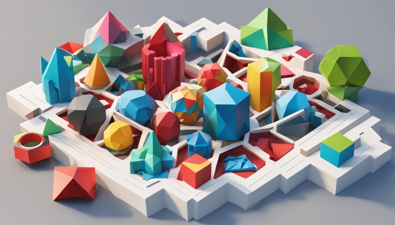
The foundation of Tinkercad’s modeling paradigm lies in its use of geometric primitive shapes, such as boxes, cylinders, and spheres. Users combine, subtract, and intersect these basic forms to construct intricate and complex designs. This constructive solid geometry (CSG) approach is intuitive, allowing designers to visualize how simple shapes interact to create a desired outcome.
A core operation in Tinkercad is ‘Grouping,’ which allows multiple shapes to be combined into a single, cohesive object. This function is essential for creating unified structures and for applying modifications to an entire assembly rather than individual components. The ‘Hole’ feature transforms any solid shape into a subtractive element, enabling precise cutouts and internal cavities within a design.
Advanced techniques involve duplicating objects with precise adjustments and utilizing the ‘Flip’ tool for symmetrical designs. These tools, combined with alignment features, enable the creation of sophisticated geometries that would typically require more advanced CAD software. The ability to quickly edit grouped shapes further streamlines the design process.
Core Principles of Beginner CAD Design
Successful 3D CAD modeling, even with simplified tools like Tinkercad, relies on foundational design principles. Starting with a clear design intent is paramount, ensuring that the purpose and functionality of the model guide the entire creation process. This initial conceptualization helps prevent unnecessary rework and maintains design integrity.
Organizing work effectively is another critical practice. While Tinkercad’s interface is straightforward, maintaining a logical structure for components and understanding how shapes interact is beneficial. Regularly inspecting the model from various angles by rotating and zooming helps identify and correct errors early in the design cycle.
Understanding the limitations and capabilities of the chosen manufacturing method, such as 3D printing, is also vital. Designing with ‘Design for Manufacturability’ (DFM) principles in mind, even at a basic level, ensures that the digital model can be successfully translated into a physical object. This includes considering factors like wall thickness and overhangs, which directly impact printability.
Preparing Models for Additive Manufacturing
After completing a 3D design in Tinkercad, the next step for physical realization is often exporting the model for 3D printing. Tinkercad supports exporting designs in several common 3D file formats, including OBJ, GLTF, and most notably, STL. The STL (Standard Tessellation Language) format is the most widely used for 3D printing due to its universal compatibility with slicing software.
When exporting, users can choose to export the entire design or only selected shapes. A significant update in Tinkercad’s export functionality allows shapes to remain ungrouped in the exported file if they were not grouped in the design, facilitating multi-color prints and the use of shapes as ‘modifiers’ in advanced slicers. This provides greater flexibility for downstream workflows in other 3D applications or print slicers.
Exporting an STL file from Tinkercad provides the model’s surface geometry, represented by numerous triangles. This file then needs to be imported into a ‘slicer’ program, which generates the G-code instructions for the 3D printer. The slicer determines parameters such as layer height, infill density, and support structures, which are crucial for a successful print.
Achieving dimensional accuracy in FDM 3D printing requires consideration of inherent process limitations. Standard FDM tolerances typically range from ±0.5% with a lower limit of ±0.5 mm for prototyping, though industrial machines can achieve tighter bounds. Features smaller than 0.6 mm or walls thinner than 1.0 mm may not resolve clearly or could result in fragile parts.
Tinkercad’s Role in STEM Education
Tinkercad is a powerful educational tool, widely adopted in STEM curricula to introduce students to 3D design, electronics, and coding. Its interactive and intuitive interface engages students, motivating them to explore the world of 3D modeling and fostering active participation in the learning process. The platform’s ability to make virtual models tangible through 3D printing is highly valued in educational contexts.
The application helps students develop crucial skills such as spatial reasoning, critical thinking, and problem-solving. By designing their own 3D models, students gain practical experience with concepts used in engineering and design professions, preparing them for future STEM pathways. Tinkercad’s integration with platforms like Google Classroom further streamlines the educational experience, allowing educators to assign projects, track progress, and provide feedback efficiently.
Tinkercad facilitates cross-curricular connections, integrating into subjects like science, mathematics, and art to promote interdisciplinary learning. Projects can range from designing miniature biomes to creating custom toys or room layouts, encouraging creativity and a holistic appreciation of various disciplines. This hands-on approach helps students visualize complex geometric concepts that might otherwise be difficult to grasp.