
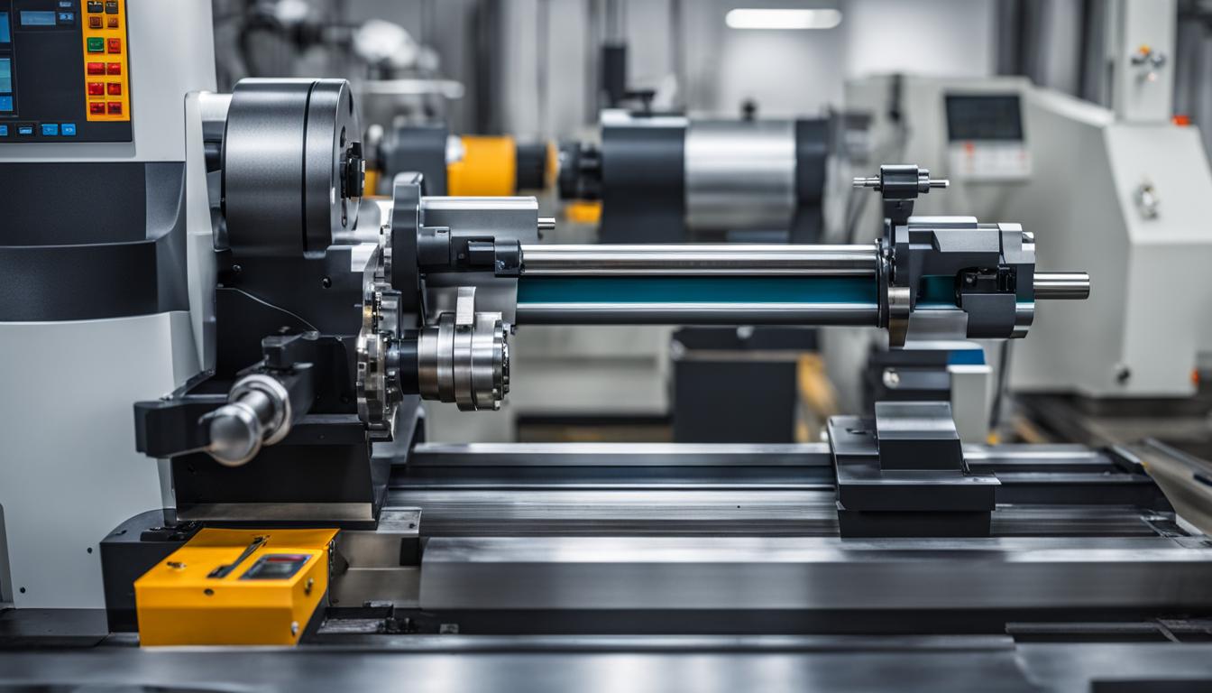
Manufacturing processes often involve shaping materials with precision, and turning is a fundamental method for creating cylindrical components. While both Computer Numerical Control (CNC) machines and manual lathes perform turning operations, their underlying principles, capabilities, and applications diverge significantly. Understanding these differences is crucial for selecting the appropriate technology for specific production requirements.
A CNC lathe is a computer-controlled machine tool primarily used for turning operations, where the machine’s actions are automated through pre-programmed software. This automation allows for precise, consistent, and efficient production of parts, making CNC lathes indispensable in modern industries such as aerospace, automotive, and medical. In contrast, a manual lathe relies entirely on a skilled machinist to control the cutting tool, feed rate, and positioning throughout the machining process.
Automation System versus Specific Machine
The core distinction between CNC and manual lathes lies in their operational control. CNC refers to Computer Numerical Control, an overarching automation system that dictates machine tool movements via coded instructions. This system transforms digital design data into precise mechanical actions, enabling complex geometries and high repeatability without constant human intervention.
Automation in CNC turning centers extends beyond basic axis movement. Modern systems integrate robotics for automated loading and unloading, automatic tool changers (ATC) to reduce downtime, and IoT-enabled monitoring for real-time data collection and predictive maintenance. These advanced features allow for ‘lights-out’ manufacturing, where machines can operate 24/7 with minimal human supervision, significantly boosting productivity and efficiency.
A manual lathe, often called a toolroom or engine lathe, is a specific machine tool where the operator directly manipulates handwheels and levers to control the cutting process. This hands-on approach provides immediate feedback through feel and sound, allowing for precise adjustments during delicate or customized work. While highly flexible for one-off jobs and small batches, manual operation inherently limits consistency and speed compared to automated systems.
Computer Numerical Control Definition
| Parameter | CNC Turning (Typical) | Manual Lathe (Typical) |
|---|---|---|
| Standard Linear Tolerance | ±0.005 inches (±0.127 mm) | ±0.002 to ±0.005 inches (operator dependent) |
| Precision Linear Tolerance | ±0.001 inches (±0.025 mm) or tighter | ±0.001 to ±0.002 inches (highly skilled operator) |
| Surface Finish (Ra) | 1.6 – 6.3 µm (standard), 0.4 – 0.8 µm (precision) | 1.6 – 3.2 µm (skilled operator), higher for roughing |
| Aluminum 6061 Cutting Speed (Carbide) | 600-1200 SFM (180-360 m/min), 800-1500 SFM (240-450 m/min) | 250 SFM (75 m/min) (HSS) |
| Stainless Steel Cutting Speed (Carbide) | 350-700 SFM (105-210 m/min) | 30-40 SFM (9-12 m/min) (HSS) |
Computer Numerical Control (CNC) defines a method of automating machine tools through pre-programmed design instructions, ensuring high accuracy and repeatability. A CNC controller, the ‘brain’ of the machine, interprets G-code and M-code, translating these digital commands into precise mechanical movements of the machine’s axes, spindle, and auxiliary systems. This process involves receiving the program, planning the motion, sending commands to hardware, and continuously monitoring the machine’s state.
Modern CNC controllers feature high-speed processing for smoother toolpaths, look-ahead technology to reduce vibration, and adaptive control for automatic feed and speed adjustments based on cutting load. They also offer user-friendly interfaces and extensive connectivity for real-time data sharing with manufacturing execution systems (MES) and enterprise resource planning (ERP) systems. This integration supports Industry 4.0 initiatives, enabling smart manufacturing environments.
Manual Lathe Capabilities
Manual lathes are versatile machines capable of producing a wide range of cylindrical parts and even some irregular shapes. A skilled machinist can perform operations such as turning, drilling, reaming, knurling, facing, and grooving. The workpiece is typically held in a chuck or collet, rotating against a stationary cutting tool that the operator controls along the X and Z axes.
These machines excel in situations requiring high flexibility, such as prototyping, repair work, or producing custom-made parts where programming a CNC machine would be inefficient. The direct tactile feedback allows for nuanced adjustments, which can be advantageous for delicate materials or complex, non-repetitive tasks. However, achieving tight tolerances and consistent surface finishes on a manual lathe heavily depends on the operator’s skill and experience.
Turned Part Geometry
CNC turning primarily creates parts with rotational symmetry, meaning their critical features share a single axis of rotation. Common examples include shafts, bushings, pins, spacers, flanges, couplings, and threaded fittings. The process involves rotating the workpiece while a cutting tool moves along and across the axis, removing material to match the CAD profile.
While traditionally limited to purely cylindrical forms, modern CNC turning centers with live tooling can incorporate secondary features like flats, slots, and cross-holes in the same setup. This capability reduces the need for additional machining operations on other machines, improving efficiency and maintaining concentricity. Turned parts are crucial for mechanical assemblies requiring rotational motion or sealing precision, demanding high dimensional accuracy and excellent surface finishes.
Standard tolerances for CNC turning typically range from ±0.005 inches (±0.127 mm) for most metals, achievable with common tooling. For applications demanding greater accuracy, such as aerospace or medical components, precision turning can achieve tolerances as tight as ±0.001 inches (±0.025 mm) or even ±0.0001 inches (±0.0025 mm) under controlled conditions. Surface finishes in CNC turning commonly range from Ra 1.6 to 6.3 µm under normal conditions, with precision turning capable of reaching Ra 0.4 µm or better with optimized parameters and tooling.
Controller Interface Integration
The controller interface is the primary point of interaction between the operator and the machine’s automation system. In CNC machines, this interface is a sophisticated hardware and software system that interprets machining programs, plans coordinated axis motion, and manages functions like spindle speed, tool changes, and safety checks. Major CNC controller platforms, such as FANUC, Siemens, Mitsubishi, Heidenhain, and Haas, each offer distinct capabilities and programming environments.
Modern CNC controller interfaces are designed for user-friendliness, featuring graphical displays, touchscreens, and integrated CAD/CAM functionalities that streamline the workflow from design to production. They provide real-time feedback on machine performance, tool wear, and operational parameters, often with advanced diagnostics and remote monitoring capabilities. This level of integration reduces operator dependency and accelerates setup times, contributing to overall manufacturing efficiency.
Manual lathes, by contrast, feature a much simpler interface consisting of handwheels, levers, and a control panel for basic functions like spindle speed and direction. Digital Readouts (DROs) are common additions to manual lathes, providing precise positional feedback for the X and Z axes, which significantly aids accuracy over traditional dials. However, the operator remains the central control unit, directly manipulating the machine’s movements and relying on their skill to achieve desired dimensions and finishes.