
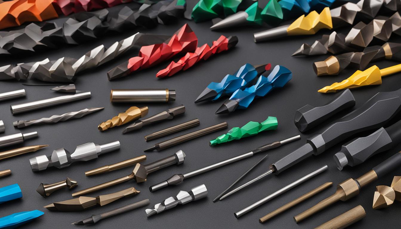
CNC router operations demand precise tool selection for optimal material removal and surface finish. Understanding the distinct geometries and applications of various router bits is fundamental for any tooling engineer. This guide explores the core bit types essential for diverse machining tasks, focusing on modern engineering practices and optimal performance.
Achieving superior cut quality and maximizing tool life hinges on selecting the correct bit for the material and desired outcome. Factors such as chip load, spindle speed, and feed rate are critical parameters that must be carefully balanced for efficient and accurate machining. Standard tolerances for general CNC woodworking typically range from ±0.005″ (±0.127 mm) to ±0.010″ (±0.25 mm), though precision applications can demand tighter specifications down to ±0.001″ (±0.025 mm).
Understanding Spiral Router Bits: Upcut vs. Downcut
Spiral router bits are categorized primarily by the direction their flutes evacuate chips: upcut or downcut. Each type offers distinct advantages depending on the machining task and material characteristics. The helix angle of the flutes dictates chip flow and the resulting finish on the workpiece’s top and bottom surfaces.
Upcut spiral bits feature flutes that pull chips upwards, away from the workpiece and towards the spindle. This design excels at efficient chip evacuation, making them ideal for deep cuts, mortises, and through-cuts where clearing debris is paramount. However, upcut bits can cause fraying or tear-out on the top surface of the material, particularly with veneered plywood or laminates.
Conversely, downcut spiral bits have flutes that push chips downwards, pressing material fibers into the workpiece. This action results in a very clean and crisp top edge, making them excellent for shallow dados, grooves, and applications where a pristine top surface is critical. A disadvantage is that downcut bits can lead to chip packing in deeper cuts, requiring slower feed rates to prevent overheating and bit breakage.
Selecting between upcut and downcut bits often involves a trade-off between chip evacuation efficiency and top surface finish. For instance, a 1/4″ (6.35mm) 2-flute carbide upcut bit in softwood might run at 16,000-18,000 RPM with a feed rate of 100-150 IPM and a chip load of 0.003-0.004 IPT.
Optimizing Plywood Machining with Compression Bits
| Bit Type | Chip Evacuation | Top Surface Finish | Bottom Surface Finish | Primary Applications |
|---|---|---|---|---|
| Upcut | Excellent (upwards) | Prone to tear-out | Clean | Deep cuts, through-cuts, mortises |
| Downcut | Poor (downwards) | Clean, crisp | Prone to tear-out | Shallow grooves, dados, clean top edges |
Compression router bits represent a specialized solution for machining double-sided laminated materials like plywood, melamine, and MDF. These bits ingeniously combine both upcut and downcut flute geometries within a single tool. The lower portion of the bit features upcut flutes, while the upper section incorporates downcut flutes.
This dual-direction cutting action effectively ‘compresses’ the material from both the top and bottom surfaces simultaneously. The upcut section lifts chips from the bottom, while the downcut section pushes fibers down from the top, resulting in exceptionally clean, tear-out-free edges on both faces of the panel in a single pass.
For optimal performance, compression bits are most effective when making full-depth cuts, ensuring both the upcut and downcut sections engage the material. If multiple passes are necessary, the initial pass must be deep enough to engage the downcut portion of the bit to prevent tear-out on the top surface.
Typical feeds and speeds for a 1/4″ compression bit in plywood or laminated chipboard might involve a spindle speed of 16,000-18,000 RPM and a feed rate of 100-140 IPM, targeting a chip load of 0.003-0.004 IPT. Some experienced operators push feed rates higher, around 325-396 IPM at 18,000 RPM, to achieve ideal chip loads of 0.009″-0.011″ for smoother cuts and reduced fuzziness.
Precision Lettering and Engraving: V-Carve Bits
V-carve bits, characterized by their conical shape and specific angle, are indispensable for intricate engraving, lettering, and chamfering tasks on CNC routers. The angle of the bit, commonly ranging from 20° to 140°, directly influences the width and depth of the cut. Sharper angles create deeper, narrower lines, while wider angles produce shallower, broader grooves.
For fine detail and small text, V-bits with acute angles like 20° or 30° are preferred, as they can create narrow lines without excessive depth. A 60° V-bit serves as a versatile all-around option for general sign carving, balancing detail with broader strokes. For bold text or chamfering, 90° V-bits are commonly employed.
When using V-carve bits, spindle speeds are typically set high, often at the machine’s maximum RPM (e.g., 18,000-24,000 RPM), to achieve a clean cut, especially at the bit’s fine tip where surface speed is inherently low. Feed rates are generally slower compared to profile cutting, with 80-120 IPM being a common starting point for wood, adjusted based on the material’s hardness and desired detail.
Achieving Complex 3D Forms with Ball Nose Bits
Ball nose bits, featuring a hemispherical cutting tip, are the go-to tools for creating smooth, contoured 3D reliefs, sculpting, and mold making on a CNC router. Their rounded profile allows for the generation of organic shapes and seamless transitions between surfaces, minimizing visible tool marks.
For high-quality 3D relief carving, tapered ball nose bits are often preferred. These bits combine a wide, rigid shank (e.g., 1/4″ or 6mm) with a small, tapered tip (e.g., 0.25mm to 1.0mm radius). This design provides superior structural strength, reducing tool deflection and enabling faster machining speeds while maintaining an excellent surface finish.
The ‘stepover’ parameter is critically important for 3D carving with ball nose bits. Stepover defines the lateral distance between successive tool passes. A smaller stepover, typically 8% to 15% of the tool’s tip diameter, yields a finer surface finish with minimal scalloping, though it significantly increases machining time.
Recommended settings for a tapered ball nose bit in hardwoods might include a spindle speed of 19,000 RPM, a feed rate of 60 IPM, and a stepover as fine as 0.0024″ (0.06mm) for ultra-fine detail. For general 3D carving, feed rates of 50-60 IPM with small stepovers are common, with adjustments based on machine rigidity and material.
Strategic Material Removal: Roughing and Finishing Bits
CNC machining often involves a two-stage process: roughing and finishing. This approach optimizes both material removal rates and final surface quality, requiring distinct bit types for each phase. Understanding their differences is key to efficient production.
Roughing bits, also known as ‘hogging’ bits, are engineered for aggressive, rapid material removal. They typically feature fewer, larger, and often serrated or corrugated flutes designed to break chips into smaller segments, reducing cutting forces and heat buildup. While highly efficient, roughing bits leave a visibly rough surface with pronounced feed marks.
Following the roughing pass, finishing bits are employed to achieve the desired dimensional accuracy and smooth surface finish. These bits typically have more flutes, smoother cutting edges, and are designed for lighter, shallower cuts. They prioritize precision and surface integrity over material removal rate.
For example, a 1/4″ flat end mill used for roughing hardwood might run at 17,000 RPM with a feed rate of 140 IPM and a depth of cut of 0.250″ per pass, aiming for a chip load of 0.005″ per tooth. In contrast, a finishing pass would utilize a higher RPM, a slower feed rate, and a much shallower depth of cut (e.g., 0.010″-0.020″) with a smaller stepover (10-20% of bit diameter) to minimize tool marks and achieve a superior finish.