
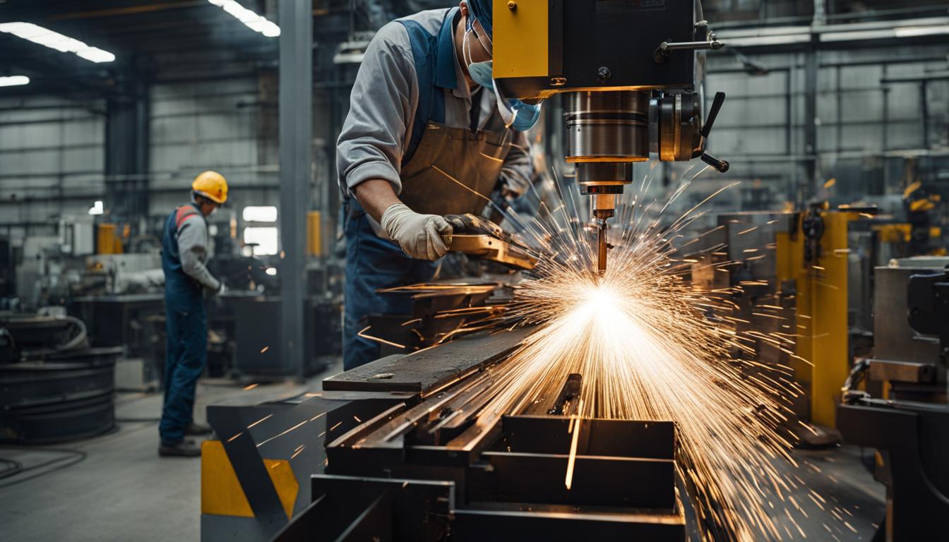
Milling machines are fundamental subtractive manufacturing tools, precisely removing material from a workpiece to achieve desired geometries. These versatile machines employ rotating multi-point cutting tools to perform a wide array of operations, from simple flat surfaces to intricate three-dimensional forms. The core purpose of these machines lies in their ability to transform raw stock into finished components with high accuracy and repeatability.
Modern Computer Numerical Control (CNC) milling machines, in particular, have revolutionized manufacturing by automating these processes. They interpret digital designs (CAD/CAM) to guide cutting tools along complex paths, ensuring consistent quality across production runs. This automation significantly reduces human error and increases production efficiency.
The Core Function of Material Removal
The primary objective of any milling operation is the controlled removal of unwanted material from a workpiece. This subtractive process begins with a solid block of material, which is then systematically cut away by a rotating tool. The tool’s geometry, rotational speed, and feed rate dictate the material removal rate and the resulting surface finish.
Different cutting tools, such as end mills, face mills, and slab mills, are selected based on the specific geometry to be created and the material being machined. Each tool features multiple cutting edges designed to shear off chips of material as it engages the workpiece. Proper chip evacuation, often aided by coolants or air blasts, is critical to prevent re-cutting chips and to manage heat generated during the process.
Achieving Flatness and Parallelism Through Facing
| Parameter | 6061 Aluminum (Carbide End Mill) | 4140 Steel (Carbide End Mill, Annealed) | Standard CNC Milling Tolerance (ISO 2768-m) | Typical As-Milled Surface Finish (Ra) |
|---|---|---|---|---|
| Cutting Speed (SFM) | 800-1200 (Roughing), 1000-1500+ (Finishing) | 250-400 | N/A | N/A |
| Chip Load (IPT, 1/2″ tool) | 0.004-0.008 (Roughing), 0.002-0.004 (Finishing) | 0.002-0.008 (General) | N/A | N/A |
| Linear Dimension Tolerance | N/A | N/A | ±0.15 mm for 50 mm nominal | N/A |
| Surface Finish (µm Ra) | N/A | N/A | N/A | 3.2 µm (125 µin) |
Creating flat and parallel surfaces is a common and critical application for milling machines. This operation, known as ‘facing,’ uses a face mill or a large-diameter end mill to machine the top surface of a workpiece. The goal is to produce a smooth, planar surface that is precisely perpendicular to the spindle axis and parallel to a reference plane.
Face mills, with their cutting inserts positioned on the tool’s face and periphery, are highly efficient for removing large amounts of material over broad areas. Achieving a fine surface finish, often specified by a Roughness Average (Ra) value, requires careful selection of cutting parameters like feed rate and step-over. Standard CNC milling typically achieves a surface roughness of Ra 1.6–3.2 µm (63–125 µin), with fine milling capable of reaching Ra 0.8 µm (32 µin) or better.
Flatness tolerances are crucial for mating components or surfaces requiring precise alignment. General tolerances for flatness are often governed by standards like ISO 2768-2, which provides classes (H, K, L) for geometric tolerances when not explicitly specified on a drawing. For precision applications, flatness can be held to within thousandths of an inch over several inches, ensuring proper assembly and function.
Crafting Features: Slots, Keyways, and Pockets
Milling machines excel at creating internal features such as slots, keyways, and pockets. Slots are elongated recesses, while keyways are specific types of slots designed to accommodate keys for transmitting torque between shafts and hubs. Pockets are enclosed cavities of various shapes and depths.
End mills are the primary tools for these operations, with their cutting edges on both the periphery and the end. Two-flute end mills are often preferred for slotting due to better chip evacuation, while multi-flute tools can offer finer finishes. Keyway milling requires adherence to specific standards, such as ANSI B17.1 or DIN 6885, which define key and keyway dimensions and tolerances.
Keyway width tolerance is particularly critical, as an oversized keyway can lead to backlash and fretting under cyclic loads. For a normal fit, hub keyway width tolerance is typically designated Js9 in metric standards. Precision pocketing often involves roughing passes to remove bulk material, followed by finishing passes to achieve the final dimensions and surface quality.
Precision Drilling and Hole Pattern Generation
While dedicated drill presses exist, milling machines are frequently used for drilling, reaming, and boring precise hole patterns. Their inherent accuracy in X-Y positioning makes them ideal for creating holes with tight positional and diameter tolerances. This is especially true for CNC milling machines, which can execute complex hole patterns with high repeatability.
Standard CNC drilling typically achieves positional accuracy of ±0.02–0.05 mm and diameter tolerance of ±0.05–0.15 mm. For tighter diameter control, drilling is often the first step in a process chain, followed by reaming (±0.005–0.02 mm diameter tolerance) or boring (±0.01–0.03 mm diameter tolerance). Reaming improves both diameter tolerance and surface finish, while boring can correct positional accuracy and achieve very tight diameter control.
Depth-to-diameter ratios are important considerations; standard drilling is typically effective for ratios below 3:1, while peck drilling can extend this to 10:1. For critical locating or dowel holes, tolerances of ±0.02 mm or better are often specified, necessitating reaming after the initial drilling operation.
Machining Complex 3D Forms
The ability to machine complex three-dimensional forms is a hallmark of advanced milling machines, particularly those with multiple axes. While 3-axis machines can create many shapes, 4-axis and 5-axis machines offer significantly enhanced capabilities. These machines can manipulate the workpiece or the cutting tool along additional rotational axes, allowing access to intricate geometries and undercuts that would be impossible with fewer axes.
Five-axis CNC machining, for instance, adds two rotational axes (typically A and B) to the standard X, Y, and Z linear axes. This enables the cutting tool to approach the workpiece from virtually any angle, often completing complex parts in a single setup. This ‘one-setup’ capability dramatically reduces setup times, improves overall accuracy by maintaining a single datum, and allows for better surface finishes due to optimal tool orientation.
Industries such as aerospace, medical, and automotive heavily rely on 5-axis milling for components like turbine blades, orthopedic implants, and engine parts. The advanced programming required for these operations is handled by sophisticated CAD/CAM software, which generates the intricate toolpaths necessary to realize complex contours and freeform surfaces.
Modern Milling Practices and Performance Metrics
Modern CNC milling machines are characterized by high rigidity, powerful spindles, and advanced control systems. These machines integrate artificial intelligence and machine learning to optimize cutting paths, predict tool failure, and ensure consistent surface finishes. This leads to fewer unplanned stops and reduced scrap rates, enhancing overall manufacturing efficiency.
Tooling advancements, including high-performance materials like cubic boron nitride (CBN) and polycrystalline diamond (PCD), further push the boundaries of what can be machined, especially for hard alloys and composites. The integration of digital twins allows for virtual commissioning and clash detection, significantly reducing setup errors and lead times.
Selecting appropriate feeds and speeds is paramount for efficient machining and tool life. These parameters vary significantly based on the material, tool type, and desired surface finish. For instance, roughing operations in 6061 aluminum with carbide end mills might use cutting speeds of 800-1200 SFM (244-366 m/min) and chip loads of 0.004-0.008 IPT for a 1/2″ diameter tool. Finishing operations often employ higher surface speeds (1000-1500+ SFM) and lower chip loads (0.002-0.004 IPT) to achieve smoother surfaces.
Machining 4140 steel, especially in its hardened condition, requires different parameters. Carbide end mills for annealed 4140 typically run at 250–400 SFM, while pre-hardened conditions necessitate lower speeds of 120–200 SFM. Coolant use is critical to manage heat and extend tool life in such demanding applications.