
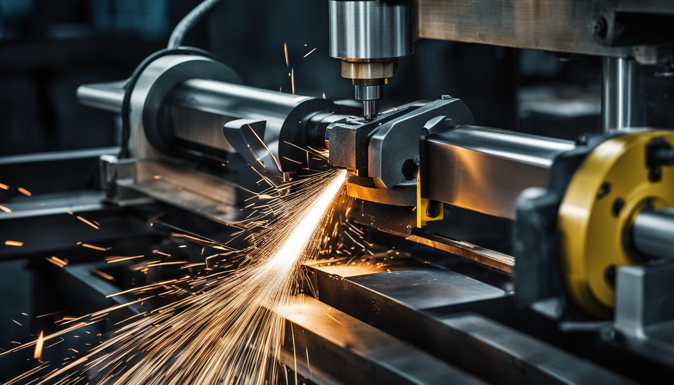
Precision manufacturing relies on a diverse array of specialized machines to shape raw metal into finished components. Each machine employs distinct principles, from mechanical shearing to thermal erosion, to achieve specific geometries, surface finishes, and dimensional tolerances. Understanding these core technologies is fundamental for any tooling engineer.
CNC Milling Machines
Computer Numerical Control (CNC) milling machines are subtractive manufacturing workhorses, removing material with rotating multi-point cutting tools. These machines offer exceptional versatility, capable of producing complex 3D geometries, slots, holes, and intricate contours. Vertical Machining Centers (VMCs) and Horizontal Machining Centers (HMCs) are common configurations, often featuring 3, 4, or 5 axes of motion for enhanced part accessibility and complexity.
Standard tolerances for CNC milling typically range from ±0.005 inches (0.127 mm) to ±0.010 inches (0.254 mm) for metal parts. Achieving tighter tolerances, such as ±0.001 inches (0.025 mm) or less, demands slower cutting speeds, high-precision tooling, and often a temperature-controlled environment.
Feeds and speeds are critical parameters in CNC milling, directly impacting tool life, surface finish, and material removal rates. For aluminum, cutting speeds often range from 200-400 m/min with feed rates of 300-500 mm/min. Steel typically requires slower cutting speeds, around 80-150 m/min, and feed rates of 200-400 mm/min.
Chip load, the amount of material removed by each tooth per revolution, is a crucial factor. For aluminum, a typical 2-flute end mill uses a 0.001–0.003 inch chip load, while carbon fiber requires smaller chip loads (0.0005–0.0015 inch) to prevent fraying. Proper chip evacuation, often aided by coolant or air blast, is essential to prevent re-cutting and built-up edge, especially with materials like aluminum.
Metal Turning Lathes
| Machine Type | Primary Cutting Mechanism | Typical Tolerance (mm) | Common Materials | Surface Finish (Ra µm) |
|---|---|---|---|---|
| CNC Milling Machine | Mechanical (rotating cutters) | ±0.127 to ±0.254 (standard) | Steel, Aluminum, Brass, Plastics | 1.6–3.2 (standard) |
| Metal Turning Lathe | Mechanical (single-point tool, rotating part) | IT8-IT7 (1.6–0.8) | Steel, Aluminum, Brass, Plastics | 0.8–1.6 (finish) |
| Fiber Laser Cutter | Thermal (focused light beam) | ±0.1 to ±0.2 | Carbon Steel, Stainless Steel, Aluminum, Copper | 3.2–6.3 (cut edge) |
| Plasma Torch Table | Thermal (ionized gas arc) | ±0.5 to ±1.5 (depending on thickness) | Mild Steel, Stainless Steel, Aluminum | 6.3–12.5 (cut edge, with dross) |
| Wire EDM | Thermal (electrical discharge) | ±0.005 to ±0.01 (standard) | Conductive metals (Tool Steel, Carbide, Titanium) | 0.2–0.8 (multi-pass) |
Metal turning lathes are fundamental machines for creating parts with rotational symmetry. They operate by rotating a workpiece against a stationary, single-point cutting tool, generating cylindrical, conical, or spherical forms. Modern CNC lathes offer high precision and repeatability for mass production, while manual lathes remain valuable for prototyping and specialized tasks.
Common operations include external turning, internal turning (boring), threading, facing, and parting-off. Advanced CNC lathes, often called ‘multitasking lathes,’ can integrate milling and drilling capabilities with powered tools, reducing setup times and increasing part complexity.
Turning accuracy generally falls within IT8-IT7 tolerance grades, with surface roughness typically ranging from 1.6 to 0.8 µm. For semi-finishing and finishing, high speeds with smaller feeds and depths of cut are employed, achieving IT10-IT7 accuracy and surface roughness of Ra 10-0.16 µm. Precision turning of non-ferrous metals with diamond tools can achieve mirror-like finishes down to Ra 0.04-0.01 µm.
Feeds and speeds in turning are defined by cutting speed (Vc) and feed rate per revolution (mm/rev). CNC lathes often utilize Constant Surface Speed (CSS) or G96 mode, which automatically adjusts RPM as the tool moves across varying diameters to maintain a consistent cutting speed. Recommended spindle speeds for aluminum with HSS tooling can be calculated based on a surface feet per minute (SFM) of 200, while brass allows for higher RPMs (12,000–14,000) with 70–90 IPM feed.
Fiber Laser Cutters
Fiber laser cutters utilize a highly concentrated light beam to melt or vaporize material along a defined path, offering high precision and minimal thermal distortion. These machines are the industry standard for high-speed processing of thin to thick metal plates, including carbon steel, stainless steel, aluminum, copper, and brass.
Laser power capacity directly correlates with material thickness capabilities. A 1.5 kW fiber laser can cut up to 16 mm carbon steel, 5 mm stainless steel, and 3 mm aluminum. Higher power systems, such as 12 kW, can process carbon steel up to 40 mm, stainless steel up to 30 mm, and aluminum up to 60 mm. Even more powerful 40 kW systems can cut carbon steel up to 100 mm.
Assist gases are crucial for effective laser cutting. Oxygen is typically used for mild steel, accelerating the cut through an exothermic reaction but leaving a thin oxide layer. Nitrogen is preferred for stainless steel and aluminum to produce bright, oxide-free edges suitable for welding or painting. Compressed air can be used for thinner aluminum and mild steel, offering a lower operating cost.
Plasma Torch Tables
Plasma torch tables cut conductive metals using a constricted, superheated stream of ionized gas. This thermal process is highly effective for thicker materials and offers faster cutting speeds than oxy-fuel for many applications. Modern high-definition plasma systems feature advanced gas consoles that automatically mix shield gases to optimize edge quality.
Recent advancements, such as the Hypertherm XPR460, have set new benchmarks, capable of piercing up to 64 mm (2.5 inches) of mild steel using argon-assist technology. These systems are increasingly used for heavy structural components, often delivering ‘bolt-ready’ precision with weld preparations and bolt holes that meet industry standards without secondary reaming.
Cutting parameters vary significantly by material. For aluminum, increasing cut speed by 20-30% over mild steel baselines helps minimize dross, with nitrogen gas recommended for superior edge quality. Stainless steel typically requires a 20% reduction in cut speed compared to mild steel, and H35 gas provides the best edge quality. Copper and brass demand even slower speeds, 30-40% less than mild steel, due to their rapid heat dissipation.
Band Saws and Wire EDM
Band saws are versatile mechanical cutting machines, employing a continuous metal strip with teeth to cut various materials. Industrial metal-cutting band saws commonly use bi-metal blades, which combine a flexible spring steel back with hardened high-speed steel teeth for durability and heat resistance. Carbide-tipped blades are reserved for high-production environments and harder materials like titanium alloys.
Blade selection depends on the material thickness and desired finish, with the ‘3-to-6 teeth in workpiece’ rule guiding tooth per inch (TPI) choices. Wider blades (20-50 mm) provide stability for straight cuts in heavy-duty materials, while narrower blades (6-10 mm) are used for contour cutting and tighter radii.
Wire Electrical Discharge Machining (EDM) is a non-contact thermal process that erodes electrically conductive materials using controlled electrical sparks from a continuously fed thin wire electrode. This method excels at machining hard, brittle, or delicate materials without mechanical force, making it ideal for intricate geometries and fine features.
Wire EDM typically uses brass or copper wire electrodes, with diameters ranging from 0.004 to 0.012 inches (0.10 mm to 0.30 mm). The process is submerged in deionized water, which flushes away debris and stabilizes the electrical discharge. Wire EDM can achieve exceptional accuracy, with standard tolerances around ±0.005–0.01 mm, and high-end machines reaching ±0.002–0.003 mm under controlled conditions with multiple skim passes. Surface finishes can be as fine as Ra 0.2–0.8 µm for precision parts.