
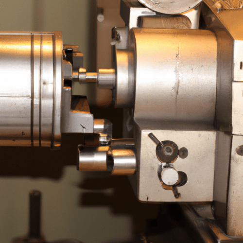
Milling is a fundamental subtractive manufacturing process that utilizes rotating multi-point cutting tools to remove material from a workpiece. This versatile machining method is crucial for creating a wide array of features, from flat surfaces and pockets to intricate threads and chamfers. Understanding the specific operations and their optimal parameters is essential for achieving precision, efficiency, and desired surface finishes in modern CNC machining.
Each milling operation demands careful consideration of tooling, feeds, speeds, and tolerances to ensure part quality and maximize tool life. Modern CNC machines, coupled with advanced cutting tools and CAM software, enable complex geometries and tight specifications across various materials, including metals, plastics, and composites. The selection of the correct milling cutter and machining strategy directly impacts the success of any given job.
Understanding Surface Face Milling
Face milling is a common operation designed to produce flat surfaces on a workpiece. The cutter’s axis is positioned perpendicular to the workpiece surface, with cutting inserts on both the face and periphery of the tool body engaging the material. This method is highly efficient for removing large amounts of material quickly and achieving a smooth, consistent finish.
Tool selection for face milling often involves indexable insert cutters, which are cost-effective due to replaceable inserts. Insert geometry, such as shape (round, square, triangular) and edge design (positive or negative rake), significantly influences cutting forces and surface finish. Positive rake inserts are suitable for softer materials, while negative rake inserts offer durability for harder materials.
Entering angles, typically 45 or 90 degrees, also play a critical role. A 45-degree entering angle provides a chip-thinning effect, reducing vibrations and allowing for increased productivity, especially in setups with long overhangs. Conversely, 90-degree entering angle face mills are used for creating right-angle edges or steps.
Optimal feeds and speeds for face milling vary significantly by material. For aluminum, speeds often exceed 300 m/min, while steel typically requires 100–200 m/min. For 300 series stainless steel, a 2.5-inch indexable face mill might run at 600–800 RPM with a 10–12 IPM feed, yielding a chip load of approximately 0.0015–0.002 inches per insert.
Efficient End Mill Pocketing Strategies
| Feature/Material | Standard Tolerance | Precision Tolerance | Typical Surface Roughness (Ra) |
|---|---|---|---|
| General Milling (Metals) | ±0.005″ (±0.13 mm) | ±0.002″ (±0.051 mm) | 3.2 µm (standard) |
| Aluminum Milling | ±0.05 mm | ±0.01 mm | 1.6 µm (fine) |
| Steel Milling | ±0.005″ (±0.13 mm) | ±0.002″ (±0.051 mm) | 0.8 µm or lower (specialized) |
| Plastics Milling | ±0.01″ (±0.25 mm) | ISO 2768-1-1989-m | N/A |
| Slot Width Tolerance | ±0.02 mm | N/A | Below Ra 1.6 µm |
Pocketing involves removing material from within a closed boundary to create a cavity or recess in a workpiece. This operation is fundamental for housing and structural components, often employing a step-down and step-over strategy to clear material efficiently.
The depth-to-diameter (D:D) ratio of the end mill is a critical factor in pocketing, directly impacting tool deflection, chip evacuation, and surface finish. Ratios up to 3:1 are considered optimal for stable machining, allowing standard feeds and speeds. As the ratio increases beyond 4:1, feed rates and depths of cut must be reduced to mitigate deflection and vibration.
Helical interpolation is a highly effective technique for pocketing, especially for creating circular pockets or controlled material entry without plunge cutting. This method coordinates simultaneous X, Y, and Z-axis movement to produce a spiral toolpath, efficiently clearing material from the center outwards in a ‘helix-out’ configuration.
For aluminum, helical pocketing might use a 50% step-over, 0.100-inch pitch, and 45-60 IPM feed. Steel applications typically require a 40% step-over, 0.050-inch pitch, and 25-35 IPM feed. Proper chip evacuation is paramount in deep pockets, often becoming the limiting factor rather than spindle power.
Precision Slotting and Grooving Techniques
Slotting and grooving operations create linear features such as straight slots, channels, grooves, and keyways. These operations are demanding on cutting tools due to the full engagement of the cutter, which generates significant forces and heat.
Tool selection for slotting is typically determined by the width and depth of the groove. End mills are versatile for closed and shallow slots, while side and face milling cutters are more efficient for long, deep, open slots, particularly on horizontal milling machines.
Modern practices often incorporate trochoidal milling strategies and adaptive toolpaths to manage radial forces and improve chip evacuation, especially in difficult materials. These techniques can reduce slotting cycle times by 30-50% and decrease tool wear significantly. When full slotting, a 35-40% feed rate reduction is often necessary compared to side-cutting to maintain tool life.
For alloy steels with carbide tools, spindle speeds should target 120–350 meters per minute, with a feed per tooth between 0.03–0.07 mm. Axial depth of cut for full-width slotting in mild steel should be limited to 0.2–0.5 inches per pass to prevent tool deflection and poor surface finish.
Chamfering and Deburring for Part Quality
Chamfering involves cutting controlled angles on sharp edges and holes, transforming them into smooth, angled transitions. This process improves safety, aids in assembly, and enhances component durability. Deburring, often performed concurrently, removes unwanted burrs left by previous machining operations.
Chamfer mills are multi-use tools capable of beveling, deburring, countersinking, engraving, and spotting, which can reduce tool changes and save time. Common chamfer types include C-chamfers (straight 45-degree cuts) and R-chamfers (rounded edges).
For chamfering steel, speeds around 400-600 SFM with appropriate chip loads can yield excellent results for tools under 32 HRC. Aluminum (6061) typically uses 300-400 SFM with a chip load of 0.001-0.003 inches per tooth for tools under 1/2 inch diameter.
Deburring directly within the CNC machine is highly efficient, completing parts in one operation and reducing manual labor costs. Specialized deburring tools, including chamfer cutters, can take advantage of multi-axis machines for complex tool paths, further increasing production efficiency.
Advanced Thread Milling and Tapping
Creating threads in a workpiece is critical for component assembly, with thread milling and tapping being the two primary methods. Thread milling uses a rotating thread mill tool following a helical path, offering high precision and flexibility. Tapping, conversely, uses a tap tool to cut threads inside a pre-drilled hole.
Thread milling excels in producing highly accurate and clean threads, is versatile across diverse materials (including hard-to-machine ones), and can create various thread sizes without tool changes. It also provides superior chip control and is less prone to tool breakage compared to tapping, especially in blind holes.
Tapping offers significant speed advantages, making it the preferred choice for high-volume production of standard threads. However, each tap is specific to one thread size and pitch, limiting its flexibility. Thread milling, while potentially slower per hole, offers greater control over the machining process and can be more economical for small batches or custom threads.
Key parameters for thread milling include thread pitch, spindle speed, cutting feed, and depth of cut. Optimal thread mill speeds typically range from 200-2000 RPM with feed rates between 0.75-4 inches per minute, depending on the material and application. For high-quality threads, full profile inserts are often preferred as they form a complete thread profile, including the crest, and often eliminate the need for post-threading deburring.