
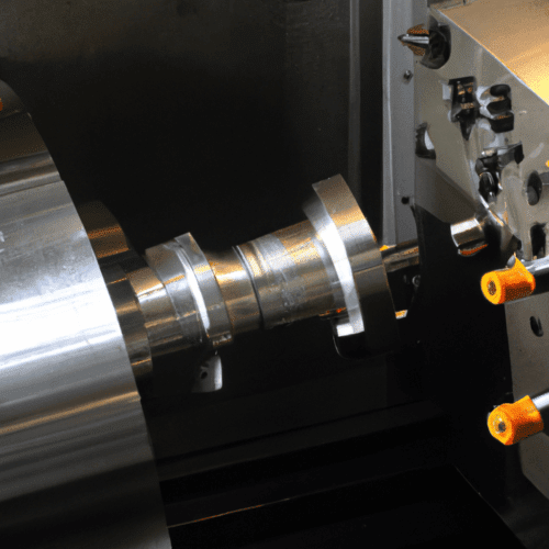
Integrated machining centers combine turning and milling operations, offering significant efficiency gains over traditional standalone machines. Distinguishing between a ‘turn-mill’ and a ‘mill-turn’ machine, however, requires a deep understanding of their fundamental architectural and operational priorities.
These multi-tasking machines are crucial for producing complex workpieces with greater efficiency and precision, often eliminating the need for multiple setups and reducing lead times. They represent a significant advancement in machining technology, merging CNC turning and milling capabilities into a single unit.
Understanding Core Machine Architectures
The primary structural difference between turn-mill and mill-turn machines lies in their foundational design, which dictates their inherent strengths. A ‘turn-mill’ machine is fundamentally a lathe with added milling capabilities. Its core structure is optimized for rotational symmetry, featuring a robust headstock and tailstock, with the workpiece typically rotating as the primary motion.
Conversely, a ‘mill-turn’ machine is built upon a milling machine platform, incorporating turning functionality. This architecture prioritizes rigidity for prismatic machining, often featuring a more substantial column and bed designed to handle significant milling forces. The workpiece may rotate, but the machine’s inherent design favors the tool’s multi-axis movement around a stationary or indexing part.
Modern turn-mill centers can range from simpler 3-axis lathes with C-axis control for milling to advanced 12-axis configurations with sub-spindles, dual turrets, and B-axis capabilities. Mill-turn machines, especially those with 5-axis capabilities, are designed for complex geometries, such as propellers or turbo impellers, where extensive milling is required.
Spindle and Workholding Dynamics
| Feature | Turn-Mill Machine | Mill-Turn Machine |
|---|---|---|
| Primary Structure | Lathe-based, optimized for turning | Milling machine-based, optimized for milling |
| Spindle Orientation | Typically horizontal, workpiece rotates for turning | Horizontal or vertical, workpiece may rotate or index |
| Axis Priority | X, Z for turning; C-axis for indexing; Y-axis optional for off-center milling | Multi-axis (e.g., 5-axis with B-axis) for complex tool paths; X, Y, Z for milling |
| Heavy Machining Focus | Heavy turning operations | Heavy milling operations |
| Tooling Capacity | Turrets with 8-12 stations (some live tooling) | Large tool magazines (26-180+ tools), comparable to machining centers |
| Typical Tolerances (Standard) | ±0.005″ (0.13 mm) on general features | ±0.005″ (0.13 mm) on linear dimensions |
| High-Precision Tolerances | Up to ±0.001″ (0.025 mm) on critical diameters | Up to ±0.001″ (0.025 mm) or better |
Spindle chucking orientation is a key differentiator. On a turn-mill machine, the main spindle typically holds the workpiece horizontally, similar to a conventional lathe, and provides the primary rotational motion for turning operations. Live tooling, often mounted on a turret, then performs milling, drilling, and tapping operations on the rotating or indexed workpiece.
Mill-turn machines can feature various spindle orientations, including horizontal or vertical configurations, depending on the machine’s design and intended applications. Vertical mill-turn machines, for instance, are adept at machining large, heavy, or oddly shaped workpieces, leveraging gravity for stable workholding.
Many advanced mill-turn centers incorporate both main and counter-spindles, allowing for complete multi-sided machining and simultaneous operations. This dual-spindle setup significantly reduces part handling and setup times, enhancing overall efficiency and accuracy.
Axis Priority Configuration
Axis priority configuration reflects the machine’s primary operational focus. Turn-mill machines prioritize the X and Z linear axes for turning, with the C-axis providing controlled spindle rotation for angular positioning during milling. The addition of a Y-axis, which moves perpendicular to the X-axis, enables off-center drilling and contour milling on cylindrical surfaces.
Mill-turn machines, particularly those with 5-axis capabilities, prioritize complex tool movements around the workpiece. These machines often feature a B-axis, which allows the milling spindle or tool head to tilt, providing greater flexibility for simultaneous 5-axis machining of intricate geometries.
Programming for mill-turn machines can involve various modes, including standard 3-axis programming (X, Y, Z) for machines with full linear axes, or XZC mode for machines without a dedicated Y-axis. Some controllers also utilize ‘TRANSMIT’ mode, which translates XYZ programs into XZC motions, optimizing for the machine’s kinematics.
Machining Focus: Heavy Turning versus Heavy Milling
Turn-mill machines excel at heavy turning operations, leveraging their robust lathe-based structure to remove significant material from cylindrical workpieces. Their main spindles are designed for high torque and rigidity during continuous rotation, making them ideal for shafts, pins, and bushings.
Mill-turn machines, with their mill-based foundation, are engineered for heavy milling tasks, offering superior rigidity and torque for prismatic features, complex contours, and hard material machining. They often feature higher milling spindle RPMs and more robust tool changers compared to live tooling on a turn-mill.
Standard CNC machining tolerances typically range around ±0.005″ (0.13 mm) for most linear dimensions in both milling and turning. For high-precision applications, tolerances as tight as ±0.001″ (0.025 mm) or even ±0.0002″ (0.00508 mm) can be achieved with advanced machines and techniques.
Feeds and speeds are critical for optimizing performance. For example, a 1/4-inch carbide end mill in 6061 aluminum might run at 10,700 RPM with a feed rate of 80 IPM, assuming a 0.0025″ chip load. These parameters are highly dependent on material, tool geometry, and machine rigidity, with spindle rigidity, horsepower, and torque setting the practical limits.
Tooling and Capacity Considerations
Tooling turret capacity differs significantly between the two machine types. Turn-mill machines, being lathe-centric, typically feature turrets with 8 to 12 tool stations, some of which are equipped with live tooling for milling operations. A 12-station turret might support live tooling on 6 stations, for instance.
Mill-turn machines, designed for extensive milling, often boast much larger tool magazines, comparable to those found on dedicated machining centers. Capacities can range from 26 tools on some models to 60 or even 180 tools on high-end machines, providing maximum flexibility for complex parts requiring numerous operations.
The ability to accommodate a wide array of tools, including specialized milling cutters, drills, and taps, is a hallmark of mill-turn centers. This expanded capacity minimizes tool changes and allows for complete part machining in a single setup, further enhancing efficiency and accuracy.