
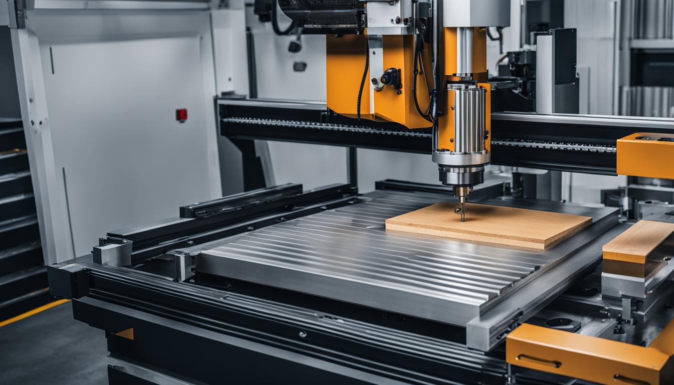
Effective part design significantly influences the overall cost of CNC machining operations. Engineers can implement several practical strategies to streamline manufacturing processes and minimize expenses. These methods focus on simplifying geometry and optimizing material removal, directly impacting cycle times and tooling wear.
Understanding the direct correlation between design choices and manufacturing expenditure is paramount for any tooling engineer. Small adjustments in a CAD model can lead to substantial savings over production runs, making design for manufacturability (DFM) a critical discipline.
Optimizing Internal Radii for Cost Efficiency
Standardizing internal radii is a fundamental approach to reducing CNC machining costs. End mills, the primary tools for creating internal corners, have a fixed radius. Specifying a radius smaller than the available tool often necessitates smaller, more fragile tools or multiple passes, increasing machining time and tool breakage risk.
Designers should aim for internal radii that are at least 1.5 times the diameter of the smallest end mill used for the feature, or ideally, larger. Common standard end mill diameters include 1/8 inch, 1/4 inch, 3/8 inch, and 1/2 inch. Therefore, internal radii like 0.0625 inches (1/16″), 0.125 inches (1/8″), 0.1875 inches (3/16″), or 0.250 inches (1/4″) are often cost-effective choices.
Larger radii allow for the use of larger, more rigid tools, which can operate at higher feeds and speeds, removing material more efficiently. This reduces cycle times and extends tool life, directly contributing to lower per-part costs. Avoiding sharp internal corners (zero radius) is crucial, as these require specialized, often slower, machining techniques like EDM or micro-milling, significantly escalating expenses.
Minimizing Deep Pockets and Complex Features
| Tolerance (inches) | Tolerance (mm) | Cost Impact | Common Applications |
|---|---|---|---|
| ±0.005 | ±0.127 | Low | General fit, non-critical dimensions |
| ±0.002 | ±0.0508 | Medium | Standard fits, mating surfaces |
| ±0.001 | ±0.0254 | High | Precision fits, bearing surfaces |
| < ±0.001 | < ±0.0254 | Very High | Aerospace, medical, optical components |
Deep pockets present significant challenges in CNC machining, leading to increased costs due to longer tools, chip evacuation issues, and potential tool deflection. The aspect ratio of a pocket (depth to width) is a critical consideration. Pockets deeper than three to four times their width generally become problematic.
When deep pockets are unavoidable, consider breaking them into multiple features or incorporating through-holes where possible to reduce the required depth of cut. Tapered walls can also aid in chip evacuation and reduce tool wear, though they add complexity to the design and programming.
Complex geometries, such as intricate contours or thin walls, also drive up costs. These features often demand smaller tools, slower feed rates, and more intricate toolpaths, extending machining time. Simplifying part geometry wherever functionally permissible can yield substantial savings.
Applying Practical Tolerances
Unnecessarily tight tolerances are a primary cost driver in CNC machining. Every increment of precision adds to machining time, tooling requirements, and inspection costs. Specifying a tolerance tighter than functionally required is a common design error that directly impacts the bottom line.
Standard CNC milling operations can typically hold tolerances of ±0.005 inches (±0.127 mm) without significant cost implications. For features requiring higher precision, ±0.002 inches (±0.0508 mm) is achievable but will increase costs. Tighter tolerances, such as ±0.001 inches (±0.0254 mm) or less, often necessitate specialized machines, environmental controls, and extensive post-machining inspection, leading to substantial cost increases.
Designers should apply geometric dimensioning and tolerancing (GD&T) principles judiciously, only specifying tight tolerances on critical features that directly affect part function or assembly. Looser tolerances on non-critical dimensions allow for faster machining and less stringent quality control, optimizing overall production costs.
Streamlining Machine Setups
Reducing the number of machine setups is a highly effective strategy for cutting CNC machining costs. Each setup requires time for fixturing, tool changes, datum setting, and inspection, all of which add non-value-added time to the manufacturing process. Minimizing setups directly translates to shorter lead times and lower labor costs.
Design parts to allow for as many features as possible to be machined in a single clamping operation. This often involves considering how the part will be held and oriented on the machine. Utilizing 5-axis machining centers can significantly reduce setups by allowing access to multiple faces of a part without re-fixturing, though the machine time itself might be higher.
Incorporating features like chamfers instead of fillets on external edges, or designing for common workholding solutions, can also simplify setups. Designers should collaborate closely with machinists to understand the practical implications of their designs on fixturing and tool access.
Leveraging Standard Thread Sizes
Designing with standard thread sizes is a straightforward yet impactful way to reduce CNC machining costs. Non-standard threads require custom taps or thread mills, which are more expensive and may have longer lead times. Furthermore, programming for non-standard threads can be more complex and prone to errors.
Commonly available thread sizes, such as M3, M4, M5, M6, M8, M10, and M12 for metric, or #4-40, #6-32, #8-32, #10-24, 1/4-20, 5/16-18, and 3/8-16 for imperial, are readily supported by standard tooling. Using these ensures tool availability and reduces setup time for tool changes.
Specifying through-holes for threads whenever possible also simplifies machining by eliminating the need for bottoming taps and reducing chip evacuation issues. When blind holes are necessary, ensure adequate thread relief at the bottom to prevent tap breakage and ensure full thread engagement.