
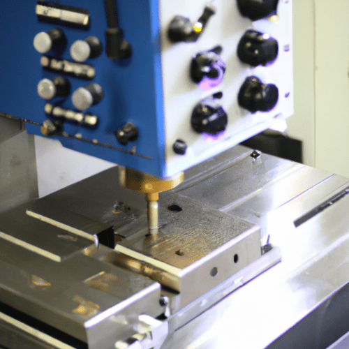
Computer Numerical Control (CNC) machines represent a cornerstone of modern manufacturing, transforming raw materials into intricate components with unparalleled accuracy. These sophisticated systems integrate computer technology with mechanical operations, enabling automated and highly precise fabrication across diverse industries. The core functionality relies on digital instructions guiding every tool movement.
CNC technology encompasses a broad spectrum of processes, from milling and turning to specialized methods like Electrical Discharge Machining (EDM) and waterjet cutting. This versatility allows manufacturers to tackle complex geometries and work with a wide array of materials, from soft plastics to hardened metals.
Understanding Computer Numerical Control
Computer Numerical Control fundamentally involves using pre-programmed computer software to dictate the movement of factory tools and machinery. This digital control replaces manual operation, ensuring consistent and repeatable production outcomes. The process typically begins with a CAD model, which is then translated into machine-readable instructions by CAM software.
The machine’s controller interprets these instructions, translating them into precise movements of the cutting tool along multiple axes. This automated workflow minimizes human error and significantly boosts production efficiency. Modern CNC systems often feature advanced capabilities, including multi-axis machining for complex part geometries.
CNC machines utilize various motion control systems to execute tool paths accurately. Point-to-point positioning directs the tool to specific coordinates, ideal for drilling operations. Linear positioning moves the tool along a straight line for straight cuts, while contouring path systems control multiple axes simultaneously to create curved shapes and complex parts.
The Role of Closed-Loop Feedback Systems
| CNC Process | Standard Tolerance (inches) | Standard Tolerance (mm) | High-Precision Tolerance (inches) | High-Precision Tolerance (mm) |
|---|---|---|---|---|
| 3-axis CNC Milling | ±0.005″ | ±0.13 mm | ±0.001″ | ±0.025 mm |
| 5-axis CNC Milling | ±0.005″ | ±0.13 mm | ±0.001″ | ±0.025 mm |
| CNC Lathe | ±0.005″ | ±0.13 mm | ±0.001″ | ±0.025 mm |
| CNC Router | ±0.005″ | ±0.13 mm | ±0.002″ | ±0.05 mm |
Closed-loop feedback systems are critical for maintaining the high accuracy and repeatability characteristic of CNC machining. These systems continuously monitor the actual position and velocity of machine axes, comparing them against the commanded trajectory. Any detected deviation triggers real-time corrections, ensuring the machine adheres precisely to the programmed path.
This ‘measure-compare-correct’ cycle is the essence of feedback in CNC systems, distinguishing them from simpler open-loop systems that operate without verifying actual movement. Core components in a closed-loop system include sensors, such as encoders or linear scales, which provide the real-time positional data.
Linear scales, for instance, measure the true table position, effectively removing errors caused by screw and coupling inaccuracies, which is particularly beneficial for high-precision applications and long axes where thermal expansion can be a factor. The continuous feedback loop enhances stability and allows for higher accelerations and better contouring, especially under varying loads.
Efficiency Through Automated Tool Changes
Automated Tool Changers (ATCs) are sophisticated mechanisms that allow CNC machines to switch between different cutting tools without manual intervention, significantly improving operational efficiency. This capability is vital for complex, multi-step machining tasks that require a variety of tools.
The ATC system operates through a servo-driven or pneumatic mechanism, rapidly removing the current tool and loading the next one from a tool magazine. This automated exchange is synchronized with the CNC program, minimizing downtime and maintaining precision throughout the machining process.
Common ATC types include carousel (or rotary) changers, which are compact and suitable for fewer tools, and chain-type changers, offering high capacity for operations requiring a large number of tools, such as in aerospace or automotive machining. Arm-type ATCs are often favored for high-speed machining due to their rapid tool exchange capabilities.
Achieving High Precision and Repeatability
High precision and repeatability are hallmarks of CNC machining, enabling the production of parts with extremely tight tolerances. Standard CNC machining operations typically achieve tolerances around ±0.010 inches (±0.25 mm), which is sufficient for a vast majority of mechanical components.
For applications demanding greater accuracy, such as medical devices or aerospace components, tighter tolerances down to ±0.005 inches (±0.13 mm) or even ±0.001 inches (±0.025 mm) are achievable. Achieving these tight tolerances requires careful consideration of machine performance, material properties, and environmental conditions.
Modern engineering practices for precision include staged roughing and finishing passes, balanced material removal to limit part movement, and thermal error compensation. In-machine probing and metrology systems also verify critical features during machining, allowing for automatic offset adjustments to counteract tool wear.
The following table outlines typical standard and high-precision tolerances for various CNC machining processes:
These values represent general guidelines; specific machine capabilities, material characteristics, and tooling can influence achievable precision. Always consult with your machinist or machine manufacturer for definitive tolerance capabilities for a given project.
Mastering G-Code for Machine Operation
G-code serves as the universal programming language that communicates instructions to CNC machines, dictating every aspect of tool movement, speed, and function. It is a series of commands that tell the machine ‘how’ and ‘where’ to move, forming the backbone of any CNC operation.
Each line of G-code, often referred to as a ‘block,’ contains specific instructions. For example, ‘G01 X10 Y5 F100’ commands a linear feed move to coordinates X10, Y5 at a feed rate of 100 units per minute. The ‘G’ in G-code stands for ‘Geometry,’ indicating commands related to motion.
Common G-codes include G00 for rapid positioning, G01 for linear interpolation (straight cuts), and G02/G03 for clockwise and counter-clockwise circular interpolation, respectively. Other essential G-codes manage work offsets (G54), plane designations (G17, G18, G19), and cutter compensation (G40, G41, G42).
Beyond G-codes, M-codes (Miscellaneous codes) control machine functions not directly related to geometry, such as spindle on/off (M03/M05), tool changes (M06), and coolant activation (M08/M09). Understanding both G-codes and M-codes is fundamental for effective CNC programming and machine operation.