
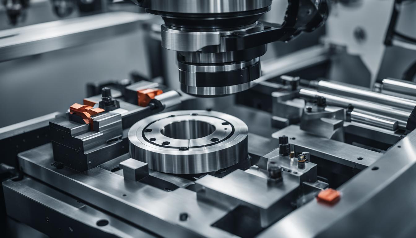
Precision machining involves a suite of advanced manufacturing processes designed to produce components with exceptionally tight tolerances and superior surface finishes. These methods are critical across industries such as aerospace, medical, and automotive, where part accuracy directly impacts performance and safety. Modern facilities leverage computer numerical control (CNC) technology to achieve the consistency and repeatability demanded by today’s complex designs.
CNC Milling and Turning Fundamentals
CNC milling utilizes rotating multi-point cutting tools to remove material from a stationary workpiece, creating intricate three-dimensional shapes. Machines typically operate along X, Y, and Z axes, with advanced systems incorporating additional rotary axes for complex contouring and multi-surface machining. This process is fundamental for producing prismatic parts, slots, pockets, and complex 3D surfaces.
CNC turning, conversely, involves rotating the workpiece while a stationary, single-point cutting tool removes material to create cylindrical features. This method excels at producing symmetrical parts like shafts, bushings, and gears with high accuracy. Modern CNC turning centers often feature live tooling and sub-spindles, enabling simultaneous milling and drilling operations without additional setups.
Standard CNC machining operations typically achieve tolerances around ±0.005 inches (±0.127 mm) for metals, suitable for general-purpose parts and prototypes. For more critical features, precision machining can reach ±0.001 inches (±0.0254 mm) or better, with industry leaders achieving 1-3 micron tolerances for demanding applications. Surface finishes for standard milling and turning generally range from Ra 3.2 μm (125 μin).
Optimizing feeds and speeds is crucial for tool life and surface quality. Spindle speed (RPM) and feed rate (linear speed) must be carefully balanced based on material, tool type, and operation. Excessive speeds can lead to tool wear and poor finishes, while slow speeds may reduce efficiency. Modern CAM software assists in generating these parameters, though experience remains vital for fine-tuning.
Achieving Precision with Grinding Operations
| Process | Typical Surface Finish (Ra) | Notes |
|---|---|---|
| Standard CNC Milling | 3.2 μm (125 μin) | Default as-milled finish |
| Fine CNC Milling | 0.8 μm (32 μin) | Achievable with optimized parameters |
| Standard CNC Turning | 1.6 μm (63 μin) | Common for general turning |
| Fine CNC Turning | 0.4 μm (16 μin) | Achievable with finishing passes |
| Surface/Cylindrical Grinding | 0.2 – 0.8 μm (8 – 32 μin) | Achieves superior finishes |
| Wire EDM (Rough Cut) | 2.8 μm (112 μin) | First pass, removes slug |
| Wire EDM (Finishing Passes) | 0.25 – 0.9 μm (10 – 35 μin) | Multiple passes for smoother finish |
Precision grinding processes are essential for achieving surface finishes and dimensional accuracies beyond what milling or turning can reliably deliver. These abrasive methods remove material in microscopic increments, reducing cutting forces and minimizing distortion, especially on hardened parts. Grinding is typically a finishing pass, following initial machining and heat treatment.
Surface grinding produces exceptionally flat and precise faces, crucial for mounting surfaces or sealing components. This process uses a rotating abrasive wheel brought into contact with a flat workpiece, ensuring high degrees of flatness, parallelism, and fine surface finishes. Tolerances can reach up to ±0.0001 inches (±0.0025 mm) with surface finishes around 0.8 Ra (32 μin) or finer.
Cylindrical grinding, conversely, focuses on truing outside diameters of rotating parts, such as shafts, pins, and spindles. It achieves superior roundness, straightness, and concentricity, critical for high-speed rotating applications. This method can hold diameter tolerances of ±0.0001 inches (±0.0025 mm) or tighter, with surface finishes often below 8 microinches Ra (0.2 μm).
Wire EDM for Intricate Geometries
Wire Electrical Discharge Machining (EDM) is a non-contact, electrothermal process that precisely cuts electrically conductive materials using a thin, continuously fed wire electrode. This method excels at creating intricate contours, narrow slots, and sharp internal corners that are challenging or impossible with conventional machining. Deionized water flushes away eroded material and cools the workpiece.
The wire, typically brass or copper, never physically touches the workpiece, eliminating mechanical stress and part deformation. This makes Wire EDM ideal for delicate or thin-walled components and for machining hardened materials like tool steels, carbides, and titanium alloys after heat treatment. Wire diameters range from 0.004 to 0.012 inches (0.10mm to 0.30mm), allowing for fine detail.
Wire EDM can achieve extremely tight tolerances, often within ±0.0002 inches (±0.005 mm) for high-precision applications. Surface finishes can be exceptionally smooth, reaching as low as 3 microinches Ra (0.075 μm) with multiple finishing passes. A rough cut typically yields Ra 112 μin (2.8 μm) with tolerances of ±0.002 inches (±0.05 mm).
Swiss-Type Lathes for Micro-Machining
Swiss-type automatic lathes, also known as sliding headstock lathes, are specialized CNC machines designed for high-volume production of small, complex, and high-precision cylindrical parts. Originating from the Swiss watchmaking industry, these machines are renowned for their exceptional accuracy and efficiency. They are particularly suited for parts with high length-to-diameter ratios.
A key feature of Swiss lathes is the guide bushing, which supports the bar stock directly at the cutting zone. This minimizes workpiece deflection and vibration, enabling consistent machining of long, slender components with tight tolerances. The sliding headstock feeds the material through the bushing as tools engage.
Modern Swiss-type lathes integrate multiple axes, live tooling, and sub-spindles, allowing for simultaneous turning, milling, drilling, and threading operations in a single setup. This ‘done-in-one’ capability reduces cycle times, eliminates secondary operations, and improves overall part accuracy and consistency. Typical part diameters range from 2 mm to 38 mm, with optimal performance often between 1 mm and 20 mm.
Swiss machining routinely achieves diametric tolerances of ±0.0005 inches to ±0.001 inches (12.7 µm to 25.4 µm) in production environments. Under controlled conditions, tolerances as tight as ±0.0001 inches (2.5 µm) are achievable. This level of precision makes Swiss lathes indispensable for medical devices, aerospace fasteners, and electronic connectors.
Quality Assurance with CMM Inspection
Coordinate Measuring Machines (CMMs) are indispensable metrology tools in modern manufacturing, verifying dimensional accuracy and geometric characteristics of manufactured parts. CMMs use a probe to collect precise X, Y, and Z coordinate data from an object’s surface, comparing it against CAD models or engineering drawings. This ensures components meet specified tolerances and design requirements.
High-precision CMMs offer unparalleled accuracy and repeatability, crucial for industries like aerospace, medical, and automotive. Standard bridge CMMs achieve volumetric accuracy in the range of ±1 to ±5 µm (±0.00004 to ±0.0002 inches) under controlled conditions. Ultra-precision CMMs can reach sub-micron accuracy, below 0.5 µm (0.00002 inches), for highly critical applications.
CMMs evaluate various geometric dimensioning and tolerancing (GD&T) features, including flatness, concentricity, parallelism, and true position. Regular calibration, typically annually, is vital to maintain accuracy, though high-volume or ultra-tight tolerance applications may require more frequent verification. Environmental factors like temperature and vibration significantly influence measurement results, necessitating controlled metrology environments.