
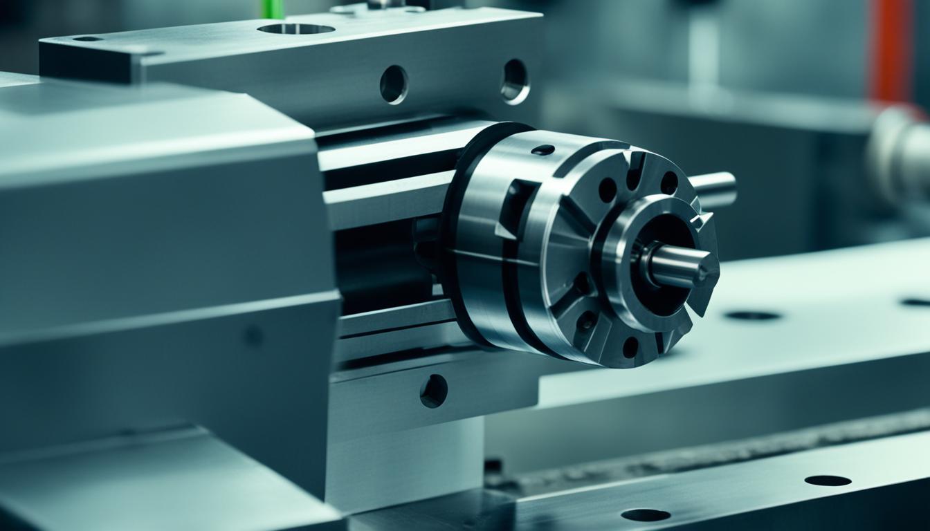
The knee mill, often exemplified by the iconic Bridgeport design, remains a fundamental machine tool in manufacturing, valued for its versatility and robust construction. Its distinct vertical column and adjustable knee mechanism provide a stable platform for precise material removal operations. These machines are essential for a wide array of machining tasks, from prototyping to toolroom operations.
The Enduring Design of Bridgeport-Style Knee Mills
Bridgeport-style knee mills are characterized by their vertical spindle orientation and a movable ‘knee’ that supports the worktable. This design allows for significant vertical adjustment of the workpiece relative to the spindle. The machine’s main components include a heavy cast iron base, a column, a knee, a saddle, a table, and a ram with a spindle head.
The robust construction, often featuring hand-scraped ways, ensures optimal machine geometry, rigidity, and accuracy over extended periods of use. Hand-scraping meticulously fits and aligns each surface, enhancing wear resistance and promoting smooth, friction-free movement. This craftsmanship contributes significantly to the machine’s longevity and consistent performance.
Many knee mills feature a patented 2J head, engineered with an efficient air-flow system to maintain optimal temperatures for the headstock, bearings, belts, and pulleys. This thermal management helps preserve accuracy and extends the lifespan of critical components, minimizing maintenance and downtime. Spindle motor horsepower typically ranges from 2 HP continuous to 5 HP peak, providing ample power for various materials.
Precision Vertical Movement: Knee and Quill Mechanics
| Parameter | Typical Range / Value (Bridgeport Series I Style) | Notes |
|---|---|---|
| Table Size | 9″ x 42″ to 12″ x 58″ | Common sizes, larger tables for heavier workpieces. |
| Spindle Motor Power | 2 HP (continuous) to 5 HP (peak) | Higher HP for heavier cuts and larger tooling. |
| Spindle Speed Range | 60 – 4200 RPM (variable speed) | Low range for torque, high range for smaller tools/finishing. |
| Spindle Taper | R-8 (standard), NMTB30 (optional) | R-8 for versatility, NMTB30 for rigidity. |
| Quill Travel | 5 inches | Essential for drilling and boring depth control. |
| Knee Travel | 16 inches | Primary Z-axis adjustment for workpiece height. |
| Manual Milling Tolerance | ±0.002″ (general) to ±0.001″ (skilled operator/DRO) | Depends heavily on operator skill and machine condition. |
| CNC Knee Mill Tolerance | ±0.005″ (standard) to ±0.0005″ (precision features) | Achievable with modern controls and glass scales. |
Vertical positioning on a knee mill is achieved through two primary mechanisms: the knee and the quill. The knee, a substantial casting, moves vertically along the column’s ways, carrying the entire saddle and table assembly. This movement provides the primary Z-axis travel for adjusting the workpiece height, typically offering around 16 inches of travel on a standard Bridgeport Series I mill.
Independent of the knee’s position, the spindle itself is housed within a quill, which provides an additional, shorter stroke of axial movement. This quill travel, usually about 5 inches on Bridgeport-style machines, is crucial for drilling, boring, and precise depth control during milling operations. It allows the cutting tool to advance into the workpiece without altering the overall table height.
Operators control the quill’s vertical motion using a hand lever for rapid adjustments or a fine-feed handwheel for incremental, precise depth settings. The fine-feed mechanism is particularly useful for delicate operations requiring accuracy to within ±0.001 inches, such as touching off or boring to specific depths.
Controlling the Cut: Spindle Feed and Tool Engagement
The spindle in a knee mill rotates the cutting tool, and its speed is adjustable to suit different materials and tooling. Older machines might use a step pulley system, while many modern knee mills feature variable speed headstocks, often controlled electronically via an inverter drive. This allows for a wide range of RPMs, from as low as 60 RPM to over 4000 RPM, providing flexibility for various machining tasks.
Quill spindle feed can be manual or power-assisted. Manual feed is engaged via a hand lever or the fine-feed handwheel, offering direct operator control. For automated drilling or boring, power quill feed mechanisms are common, providing selectable feed rates. Typical power feed rates on a Bridgeport Series I include 0.0015, 0.003, and 0.006 inches per revolution.
Tooling is secured in the spindle using a taper system, with the R-8 taper being standard for many Bridgeport-style mills due to its ease of use and quick tool changes. Some machines also offer an NMTB30 taper option for heavier-duty applications. The taper design ensures even distribution of machining loads, reducing tool wear and prolonging machine life.
Achieving Accuracy: Manual Positioning and Digital Readouts
Manual positioning on a knee mill relies on handwheels for X, Y, and Z-axis movements, with precision dependent on operator skill and the machine’s mechanical condition. Machinists use dials, measuring tools, and edge finders to locate features and control dimensions. For general manual milling, a practical accuracy range is around ±0.05 mm (approximately ±0.002 inches).
Digital Readout (DRO) systems significantly enhance the precision and efficiency of knee mills. A DRO provides real-time, on-screen position feedback for each axis, eliminating the need to count handwheel revolutions and reducing errors caused by backlash. This direct measurement of table or slide movement improves accuracy and repeatability.
A 3-axis DRO is highly recommended for milling machines, tracking X, Y, and Z movements. While the X and Y axes are straightforward, the Z-axis can be mounted on either the knee or the quill. Mounting the Z-axis DRO on the quill is often preferred for drilling and boring operations, offering finer resolution and independent depth tracking.
Modern DRO systems offer features like bolt-hole circle calculations, linear pattern spacing, and tool offset libraries, further streamlining common machining tasks. Shops often report a 20-40% increase in productivity after installing a DRO, making it a highly valuable upgrade for manual machines.
Knee Mills in the Modern Job Shop: Versatility and Applications
Despite the prevalence of CNC machining centers, knee mills remain indispensable in many job shops, toolrooms, and educational facilities. Their mechanical flexibility, including the ability to tilt the head and extend the ram, makes them ideal for complex setups that might be cumbersome on a dedicated CNC machine.
Knee mills excel in ‘second-op’ work, such as tapping, drilling, and light milling, where the setup time for a CNC machine would be cost-prohibitive. They are also favored for prototyping and short-run production, where operator control and fixture simplicity outweigh the need for full automation.
Many modern knee mills bridge the gap between manual and CNC, incorporating features like power feeds, digital readouts, and even 2- or 3-axis CNC controls. These hybrid machines offer the best of both worlds, combining the tactile control of a manual mill with the precision and repeatability of automated movements.
Optimizing Performance: Current Tolerances, Feeds, and Speeds
Achievable tolerances on knee mills vary based on machine condition, operator skill, and the use of DROs. For general manual milling, a practical tolerance range is around ±0.05 mm (±0.002 inches). With a well-maintained machine, DRO, quality tooling, and an experienced machinist, tighter dimensions are possible, approaching ±0.001 inches.
For CNC knee mills, standard machining tolerances are typically ±0.005 inches (0.13 mm) for most linear dimensions. Precision machining can achieve ±0.002 inches (0.051 mm), and for reamed holes, tolerances as tight as ±0.0005 inches (0.0127 mm) are attainable under controlled conditions.
Selecting appropriate feeds and speeds is critical for efficient material removal and tool life. For aluminum, a 0.250-inch, 2-flute HSS end mill might run at 2500 RPM with a feed rate of 15 inches per minute (ipm), yielding a chip load of 0.003 inches per tooth (ipt). For mild steel, a 0.250-inch, 4-flute HSS end mill could operate around 640 RPM.
When face milling on a 2-3 HP Bridgeport-class machine, using 1.5-inch to 3-inch diameter face mills is recommended, with RPM limited to 2500-3000 to prevent spindle bearing damage. Roughing operations in aluminum can achieve material removal rates of 6-8 cubic inches per minute with proper tooling and a 3 HP spindle.