
Computer Numerical Control (CNC) cutting and laser cutting represent two foundational subtractive manufacturing processes, each employing distinct methodologies to achieve material removal. While both are highly precise and automated, their underlying physical principles, operational characteristics, and application suitability diverge significantly, impacting material processing capabilities and final part quality.
Fundamental Cutting Mechanisms: Mechanical versus Thermal
CNC cutting, encompassing processes like milling, routing, and turning, relies on the mechanical action of a physical rotary bit or other cutting tool. Material removal occurs through chip formation, where the tool’s sharp edges shear, abrade, or fracture the workpiece. This direct contact process generates significant cutting forces and relies on the tool’s geometry and material hardness to overcome the workpiece’s resistance. [12, 43]
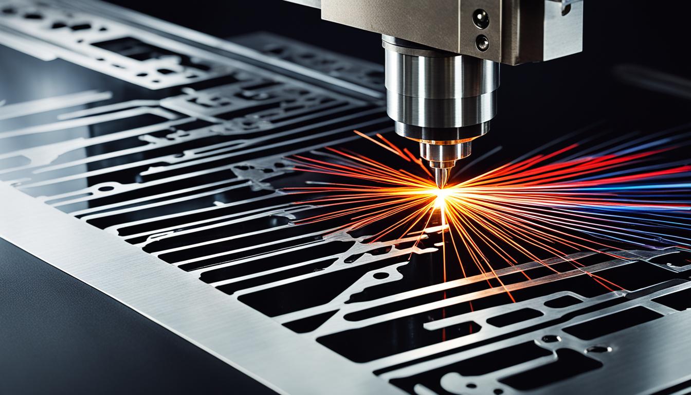
In contrast, laser cutting is a thermal separation process that utilizes a highly focused, high-power laser beam. The concentrated light energy heats the material to its melting or vaporization point, effectively burning or melting a narrow path. An assist gas, such as oxygen or nitrogen, is typically used to blow away the molten or vaporized material, ensuring a clean cut edge. [18, 20, 23, 26, 30, 31]
The core difference lies in energy transfer: CNC machines apply kinetic energy through a physical tool, while laser systems deliver electromagnetic energy as photons. This distinction dictates the types of materials each process can efficiently handle and the resulting material alterations. Laser beams do not wear down like physical tools, offering a non-contact cutting method. [17, 30, 31]
Contact Forces, Heat Zones, and Material Integrity
| Parameter | CNC Cutting (Milling/Routing) | Laser Cutting (Fiber/CO2) |
|---|---|---|
| Typical Kerf Width | ~0.5 mm to several mm (tool dependent) [4, 7] | 0.08 mm to 1.0 mm (material, power, type dependent) [1, 2, 5] |
| Standard Positional Tolerance | ±0.051 mm to ±0.13 mm (for metals) [16, 19, 25, 32, 40] | ±0.1 mm (under 6 mm thick steel) to ±0.5 mm (20 mm thick steel) [6, 21] |
| Max Mild Steel Thickness | Limited by machine/tooling (e.g., 100mm+ for milling) | Up to 25 mm (fiber laser), up to 20 mm (CO2 laser) [6, 21] |
| Heat Affected Zone (HAZ) | Minimal to none (mechanical process) | Typically 0.1 mm to 0.5 mm (material, power dependent) [6, 9] |
CNC machining involves substantial cutting forces, including tangential, radial, and axial components, which are direct results of the tool-workpiece interaction. These forces can lead to tool deflection, workpiece deformation, and vibrations, directly influencing surface finish and dimensional accuracy. Proper tool selection, machine rigidity, and optimized feeds and speeds are critical to manage these mechanical stresses. [12, 44, 45, 47]
Laser cutting, being a thermal process, introduces a ‘heat-affected zone’ (HAZ) adjacent to the cut edge. This HAZ is an area where the material’s microstructure and hardness are altered due to rapid heating and cooling, without actually melting. The width and severity of the HAZ depend on laser power, cutting speed, assist gas, and material properties, potentially leading to discoloration, distortion, or micro-cracks in sensitive materials. [9, 10, 13, 22, 28, 31]
While CNC cutting can induce residual stresses from mechanical deformation, laser cutting’s primary concern is thermal stress and its impact on material properties. For applications requiring pristine material integrity near the cut, minimizing the HAZ in laser cutting is paramount, sometimes necessitating post-processing or alternative methods like waterjet cutting for heat-sensitive alloys. [6, 10, 13, 22]
Material Thickness and Geometric Constraints
CNC cutting, particularly milling, can process a wide range of material thicknesses, from thin sheets to thick plates and solid blocks, limited primarily by machine power, tool length, and rigidity. For example, CNC milling can effectively machine steel alloys to significant depths, and routing can handle various plastics and composites. The process allows for complex 3D geometries and deep pockets. [47]
Laser cutting capabilities for material thickness vary significantly by laser type and material. Fiber lasers, for instance, can cut thin sheet metal (0.5–3 mm steel or stainless) with kerf widths typically between 0.10–0.25 mm, extending to 15–25 mm steel with higher power (6–12 kW) where kerf can reach 0.6–1.0 mm. CO2 lasers are often preferred for non-metals and thicker metals, with kerf widths typically in the 0.25–0.5 mm range for 1–6 mm steel. [1, 5, 6, 21]
Generally, CNC machining offers greater versatility for very thick materials and complex three-dimensional features. Laser cutting excels in precise 2D profile cutting of sheet materials, with its efficiency diminishing as material thickness increases due to beam divergence and increased heat input. Minimum hole sizes in laser cutting are typically around 1.5 times the kerf width, and small holes in thick plate can lose roundness. [5, 6, 21]
Kerf Width and Precision Considerations
Kerf refers to the width of material removed by the cutting process, a critical parameter for dimensional accuracy and part fit-up. In CNC machining, the kerf is primarily defined by the cutting tool’s effective diameter, though factors like tool deflection and runout can influence the actual width. [4, 7]
Laser cutting kerf width is influenced by numerous factors, including laser type (CO2 vs. fiber), power, cutting speed, focal length, assist gas type and pressure, and material properties like thickness and thermal conductivity. Fiber lasers generally produce narrower kerfs (0.10–0.5 mm) compared to CO2 lasers (0.25–0.5 mm), with kerf widening as material thickness increases. [1, 2, 3, 4, 7, 11, 15, 21]
Accurate kerf compensation is essential in both processes to achieve desired part dimensions. Without compensation, external contours become undersized, and internal features like holes become oversized. Modern CNC and laser cutting software typically incorporate automatic kerf offset capabilities to ensure precision. [2, 3, 6, 15, 46]
Tooling Longevity and Maintenance Regimes
CNC cutting tools, such as end mills, drills, and inserts, are subject to various wear mechanisms including flank wear, crater wear, built-up edge, notch wear, and chipping. These are caused by abrasion, adhesion, diffusion, and thermal stress. Tool wear directly impacts machining accuracy, surface finish, and requires regular inspection, resharpening, or replacement to maintain performance. [8, 24, 33, 34, 36]
Laser cutting systems, lacking physical cutting tools, instead require meticulous maintenance of their optical components, primarily lenses and mirrors. Contamination from dust, debris, or smoke can degrade optical performance, reduce laser power, and cause heat stress on the lens, potentially leading to breakage. Regular cleaning with approved optical solutions and lint-free materials is essential. [14, 29, 37, 41, 42]
The maintenance philosophies differ significantly: CNC focuses on managing the degradation of consumable cutting edges, while laser cutting emphasizes preserving the integrity and cleanliness of precision optics. Both approaches are critical for sustained operational efficiency and product quality, with each incurring distinct costs related to consumables and specialized cleaning or replacement parts. [8, 14, 24, 29, 33, 37]