
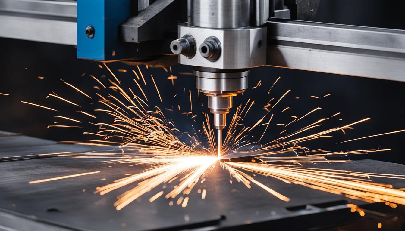
Machining metal components demands specialized equipment capable of precise material removal and intricate geometries. Computer Numerical Control (CNC) technology underpins a diverse array of machines engineered specifically for metal fabrication, each optimized for distinct processes and material characteristics.
Selecting the appropriate CNC machine for metal cutting hinges on factors such as material type, desired precision, part complexity, production volume, and required surface finish. Understanding the core capabilities of each machine type is essential for efficient and cost-effective manufacturing.
CNC Vertical Milling Centers for Complex Geometries
CNC vertical milling centers (VMCs) are foundational in metalworking, excelling at subtractive manufacturing through rotating multi-point cutting tools. These machines typically feature a vertically oriented spindle that moves along the Z-axis, while the workpiece is secured on a table that translates along the X and Y axes. Modern VMCs often incorporate 4-axis or 5-axis capabilities, allowing for highly complex part geometries and single-setup machining of multiple faces.
Common applications for VMCs include creating molds, dies, prototypes, and intricate aerospace components from various metals. They are adept at operations such as face milling, slotting, drilling, tapping, and contouring. Standard positional tolerances for high-precision VMCs can reach ±0.005 mm (±0.0002 inches), with repeatability often within ±0.0025 mm (±0.0001 inches).
Feeds and speeds for milling metal vary significantly based on material hardness, tool material, and cutter diameter. For example, machining 6061 aluminum with a carbide end mill might involve surface speeds of 200-600 meters per minute (650-2000 SFM) and feed rates of 0.05-0.2 mm/tooth (0.002-0.008 IPT). Conversely, harder materials like 304 stainless steel require lower surface speeds, typically 60-150 meters per minute (200-500 SFM), and reduced feed rates to prevent tool wear and work hardening.
CNC Metal Turning Lathes for Rotational Symmetry
| Machine Type | Primary Function | Typical Positional Tolerance (mm) | Max Material Thickness / Part Size | Typical Surface Finish (Ra µm) |
|---|---|---|---|---|
| CNC Vertical Milling Center | Complex 3D shapes, drilling, tapping | ±0.005 – ±0.025 | Up to 1000mm cube (varies) | 0.8 – 3.2 |
| CNC Metal Turning Lathe | Rotational parts, boring, threading | ±0.010 – ±0.025 | Up to 500mm diameter (varies) | 0.4 – 1.6 |
| High-Rigidity CNC Router | 2D/2.5D cutting, engraving (soft metals) | ±0.05 – ±0.1 | Up to 1500x3000mm sheets | 1.6 – 6.3 |
| Fiber Laser Cutter | High-speed 2D sheet metal cutting | ±0.02 – ±0.05 | Up to 50mm (steel) | 0.8 – 3.2 (cut edge) |
| Wire Electrical Discharge Machine (EDM) | Intricate cuts, hard materials, fine features | ±0.002 – ±0.005 | Up to 500mm thick (varies) | 0.2 – 0.8 |
CNC metal turning lathes are indispensable for producing parts with rotational symmetry, such as shafts, bushings, and flanges. These machines hold the workpiece in a chuck and rotate it at high speeds, while a stationary cutting tool removes material to achieve the desired profile. Modern CNC lathes, often called ‘turning centers,’ frequently include live tooling capabilities, allowing for secondary operations like milling, drilling, and tapping without removing the part from the machine.
Precision turning operations can achieve tight dimensional tolerances, with typical IT grades ranging from IT6 to IT7 for production parts, translating to tolerances of ±0.010 mm to ±0.025 mm (±0.0004 to ±0.001 inches) on diameters. Surface finishes can be exceptionally smooth, often reaching Ra 0.8 µm (32 microinches) or better with proper tooling and parameters.
Feeds and speeds for turning are also material-dependent. For instance, turning mild steel with a carbide insert might use cutting speeds of 150-300 meters per minute (500-1000 SFM) and feed rates of 0.1-0.4 mm/revolution (0.004-0.016 IPR). Harder alloys or interrupted cuts necessitate lower speeds and feeds to maintain tool life and part integrity.
High-Rigidity CNC Routers in Metal Fabrication
While often associated with woodworking, high-rigidity CNC routers are increasingly employed for cutting softer metals like aluminum, brass, and thin steel sheets. These machines distinguish themselves from their woodworking counterparts through robust construction, heavier gantry systems, and powerful, high-torque spindles, typically ranging from 5 kW to 15 kW (7-20 HP).
Metal-cutting CNC routers are effective for applications such as panel fabrication, engraving, and creating intricate designs in non-ferrous metals. They offer a cost-effective solution for larger sheet processing where extreme precision of a milling center is not strictly required. However, their rigidity and spindle power limit their ability to machine harder steels or thick sections compared to dedicated milling machines.
Tolerances for metal routing generally fall within ±0.05 mm to ±0.1 mm (±0.002 to ±0.004 inches), depending on machine quality, tool condition, and material. Feeds and speeds are typically lower than those used in VMCs for similar materials to manage heat generation and tool deflection. For aluminum, a router might use spindle speeds of 15,000-24,000 RPM with feed rates of 2,000-6,000 mm/min (80-240 IPM) using appropriate single-flute or O-flute end mills.
Fiber Laser Cutting Systems for High-Speed Sheet Metal Processing
Fiber laser cutters represent a significant advancement in sheet metal fabrication, offering unparalleled speed and precision for cutting various metals. These systems utilize a solid-state laser source that generates a high-power beam, delivered via an optical fiber to a cutting head. The focused laser beam melts and vaporizes the material, while an assist gas (oxygen or nitrogen) expels the molten metal, creating a clean cut.
Modern fiber lasers, with power outputs ranging from 1 kW to over 30 kW, can cut a wide array of metals including stainless steel, carbon steel, aluminum, copper, and brass. They are particularly efficient for thin to medium-thick sheets, with capabilities extending to 50 mm (2 inches) or more in steel with higher power systems.
Cutting speeds are exceptionally high; a 10 kW fiber laser can cut 1 mm (0.04 inch) stainless steel at over 30 meters per minute (1200 IPM) and 10 mm (0.4 inch) carbon steel at 2-3 meters per minute (80-120 IPM). Positional accuracy is typically ±0.02 mm (±0.0008 inches), with cut edge tolerances often within ±0.05 mm (±0.002 inches).
Wire Electrical Discharge Machines (EDM) for Intricate Cuts
Wire Electrical Discharge Machining (WEDM), commonly known as Wire EDM, is a non-conventional machining process that uses electrical discharges (sparks) to erode material from a workpiece. A thin, continuously spooling wire electrode, typically brass or zinc-coated brass, is guided through the workpiece, creating a precise cut without direct mechanical force. This process is ideal for cutting hard, electrically conductive materials that are difficult or impossible to machine with traditional methods.
Wire EDM excels at producing extremely intricate shapes, sharp internal corners, and fine features in hardened tool steels, carbides, titanium, and other exotic alloys. It is widely used in mold making, die manufacturing, and for creating precision components for aerospace and medical industries. The non-contact nature of the process eliminates mechanical stress, heat distortion, and burrs.
Achievable tolerances with Wire EDM are among the tightest in manufacturing, often reaching ±0.002 mm to ±0.005 mm (±0.00008 to ±0.0002 inches) for critical dimensions. Surface finishes can be exceptionally smooth, with Ra values as low as 0.2 µm (8 microinches) achievable through multiple skim cuts. Cutting speeds vary significantly with material type and thickness, but a typical rate for 50 mm (2 inch) thick tool steel might be 10-20 mm/minute (0.4-0.8 IPM).