
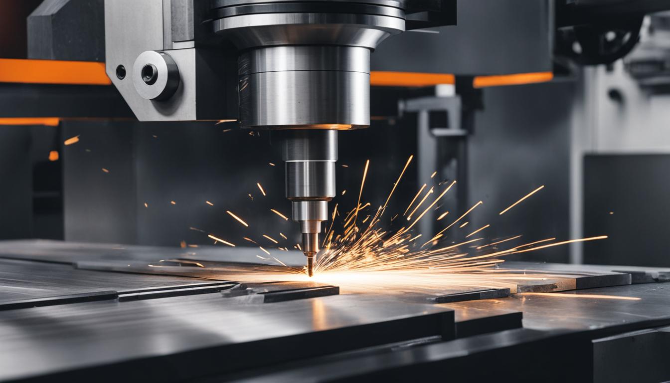
Manufacturing processes often involve removing material to achieve a desired shape and finish. This fundamental concept underpins a vast array of techniques, collectively known as machining.
Machining: the Broad Subtractive Manufacturing Discipline
Machining represents a comprehensive category of subtractive manufacturing processes. It involves the controlled removal of material from a workpiece to create a finished part with specific dimensions and surface characteristics. This broad definition encompasses numerous methods, each employing distinct tools and kinematics.
The primary goal of machining is to transform raw stock into a precisely engineered component. This can range from roughing operations that remove large volumes of material quickly to fine finishing passes that achieve tight tolerances and superior surface finishes. Material removal is typically achieved through mechanical means, such as cutting, abrasion, or erosion, fundamentally altering the workpiece’s geometry.
Modern machining practices leverage advanced computer numerical control (CNC) systems. These systems automate tool paths and machine movements, significantly enhancing precision, repeatability, and production efficiency across various industries. The integration of sophisticated CAD/CAM software streamlines the design-to-manufacturing workflow, allowing for complex geometries to be programmed and executed with high accuracy.
Beyond traditional mechanical removal, some advanced machining techniques also fall under the subtractive umbrella. These include electrical discharge machining (EDM), which uses electrical sparks to erode material, and laser cutting, which employs a focused laser beam to vaporize or melt material. While different in their energy source, their objective remains material subtraction.
Milling: a Specialized Rotary Cutting Operation
| Characteristic | Milling | Turning | Grinding |
|---|---|---|---|
| Primary Motion | Rotating cutter, moving workpiece/tool | Rotating workpiece, stationary tool | Rotating abrasive wheel, moving workpiece |
| Typical Geometry | Flat surfaces, slots, pockets, complex 3D shapes | Cylindrical, conical, spherical forms | High-precision flat, cylindrical, or contoured surfaces |
| Tool Type | Multi-point (end mills, face mills) | Single-point (inserts, brazed tools) | Multi-point abrasive wheel |
| Material Removal Rate | Medium to High | Medium to High | Low (finishing operation) |
| Achievable Tolerance | ±0.001″ to ±0.005″ (±0.025mm to ±0.127mm) | ±0.001″ to ±0.005″ (±0.025mm to ±0.127mm) | ±0.0001″ to ±0.0005″ (±0.0025mm to ±0.0127mm) |
| Surface Finish (Ra) | 32-125 µin (0.8-3.2 µm) | 32-125 µin (0.8-3.2 µm) | 4-32 µin (0.1-0.8 µm) |
Milling is a specific machining process that utilizes rotary cutters to remove material from a workpiece. The cutting tool, typically an ‘end mill’ or ‘face mill’, rotates at high speeds while the workpiece is fed into it, or the tool is fed into the workpiece. This action creates chips, progressively shaping the part.
This method is highly versatile, capable of producing a wide range of features including slots, pockets, shoulders, and complex three-dimensional contours. Milling machines are categorized by their axis capabilities, from basic 3-axis machines to advanced 5-axis systems that allow for simultaneous movement along multiple axes, enabling the creation of intricate geometries required for aerospace components or medical implants.
Common milling operations include face milling for flat surfaces, peripheral milling for edges, and slotting for channels. Tooling selection is critical, with end mills varying in flute count, helix angle, and coating to suit different materials and desired finishes. For instance, two-flute end mills are often preferred for softer materials like aluminum due to better chip evacuation.
Achieving optimal material removal rates and tool life in milling requires careful consideration of feeds and speeds. These parameters are dependent on the workpiece material, tool material, tool diameter, and machine rigidity. Incorrect settings can lead to poor surface finish, excessive tool wear, or even tool breakage, impacting both part quality and production costs.
Typical starting parameters for common materials include:
- Aluminum 6061 (2-flute carbide end mill, 1/2″ diameter): Surface Speed (SFM) 600-1200, Feed Rate (IPM) 20-60.
- 4140 Steel (4-flute carbide end mill, 1/2″ diameter): Surface Speed (SFM) 200-400, Feed Rate (IPM) 5-20.
Turning and Grinding: Diverse Machining Methods
Turning is another fundamental machining process, distinct from milling, where the workpiece rotates while a stationary, single-point cutting tool removes material. This operation is primarily used to create cylindrical or conical shapes, such as shafts, pins, and bushings. Lathes are the machine tools specifically designed for turning operations, ranging from manual engine lathes to sophisticated CNC turning centers.
The cutting tool in turning is typically a single-point tool, often made of carbide or high-speed steel, with a specific geometry designed for chip formation and evacuation. Parameters like cutting speed, feed rate, and depth of cut are precisely controlled to achieve the desired diameter and surface finish. Modern CNC turning centers can also incorporate ‘live tooling’ for secondary operations like drilling or milling on the same setup.
Grinding, conversely, is an abrasive machining process that employs a rotating abrasive wheel to remove small amounts of material. It is typically a finishing operation, used to achieve extremely high dimensional accuracy and fine surface finishes on hardened materials that are difficult to machine by other methods. Grinding can produce tolerances as tight as ±0.0001 inches (±0.0025 mm) in some applications.
The abrasive wheel consists of abrasive grains, such as aluminum oxide or silicon carbide, bonded together. As the wheel rotates and contacts the workpiece, the sharp edges of the grains cut away microscopic chips. This process generates significant heat, necessitating effective coolant systems to prevent thermal damage to the workpiece and maintain wheel integrity.
Machine Tool Types and Their Operational Principles
Machine tools are the foundational equipment enabling subtractive manufacturing. A milling machine, for example, positions and moves the cutting tool relative to the workpiece, facilitating material removal. Vertical machining centers (VMCs) and horizontal machining centers (HMCs) are common types, differing in spindle orientation and workpiece access, each offering advantages for specific part geometries and production volumes.
Lathes, essential for turning, hold the workpiece in a chuck and rotate it at controlled speeds. The cutting tool, mounted on a tool post, traverses along the workpiece’s axis to create the desired profile. Modern CNC lathes, often called ‘turning centers’, can perform complex operations including drilling, boring, and even some milling features, sometimes referred to as ‘turn-mill’ operations.
Grinding machines utilize abrasive wheels composed of countless small, hard particles bonded together. These machines come in various forms, including surface grinders for flat surfaces, cylindrical grinders for external and internal diameters, and centerless grinders for high-volume production of cylindrical parts. Each type is optimized for specific geometries and precision requirements, ensuring the final part meets stringent specifications.
Precision, Tolerances, and Modern Fabrication Scopes
Achieving precise dimensions and surface finishes is paramount in machining. Standard tolerances for general machining operations often fall within ±0.005 inches (±0.127 mm) to ±0.001 inches (±0.025 mm), depending on the process and material. Precision machining, however, can achieve much tighter tolerances, sometimes down to a few microns, which is critical for interchangeable parts and assembly.
Geometric Dimensioning and Tolerancing (GD&T) is a standardized system used to define and communicate engineering tolerances. It specifies the allowable variation in form, orientation, location, and runout of part features, ensuring functional requirements are met regardless of manufacturing variations. Adherence to standards like ASME Y14.5 is crucial for global manufacturing consistency.
Modern fabrication scopes extend beyond simple part creation to complex assemblies and integrated systems. CNC machines, with their ability to hold tight tolerances and execute intricate tool paths, are central to industries like aerospace, medical devices, and automotive, where component reliability and performance are critical. The choice between milling, turning, or grinding depends heavily on the part’s geometry, material, and required precision, often involving a combination of these methods.
The continuous advancement in cutting tool materials, machine rigidity, and control systems pushes the boundaries of what is achievable. High-speed machining (HSM) techniques, for instance, employ higher spindle speeds and lighter cuts to improve material removal rates and surface finish, particularly in mold and die making. This approach minimizes heat generation and tool wear, extending tool life and improving productivity.