
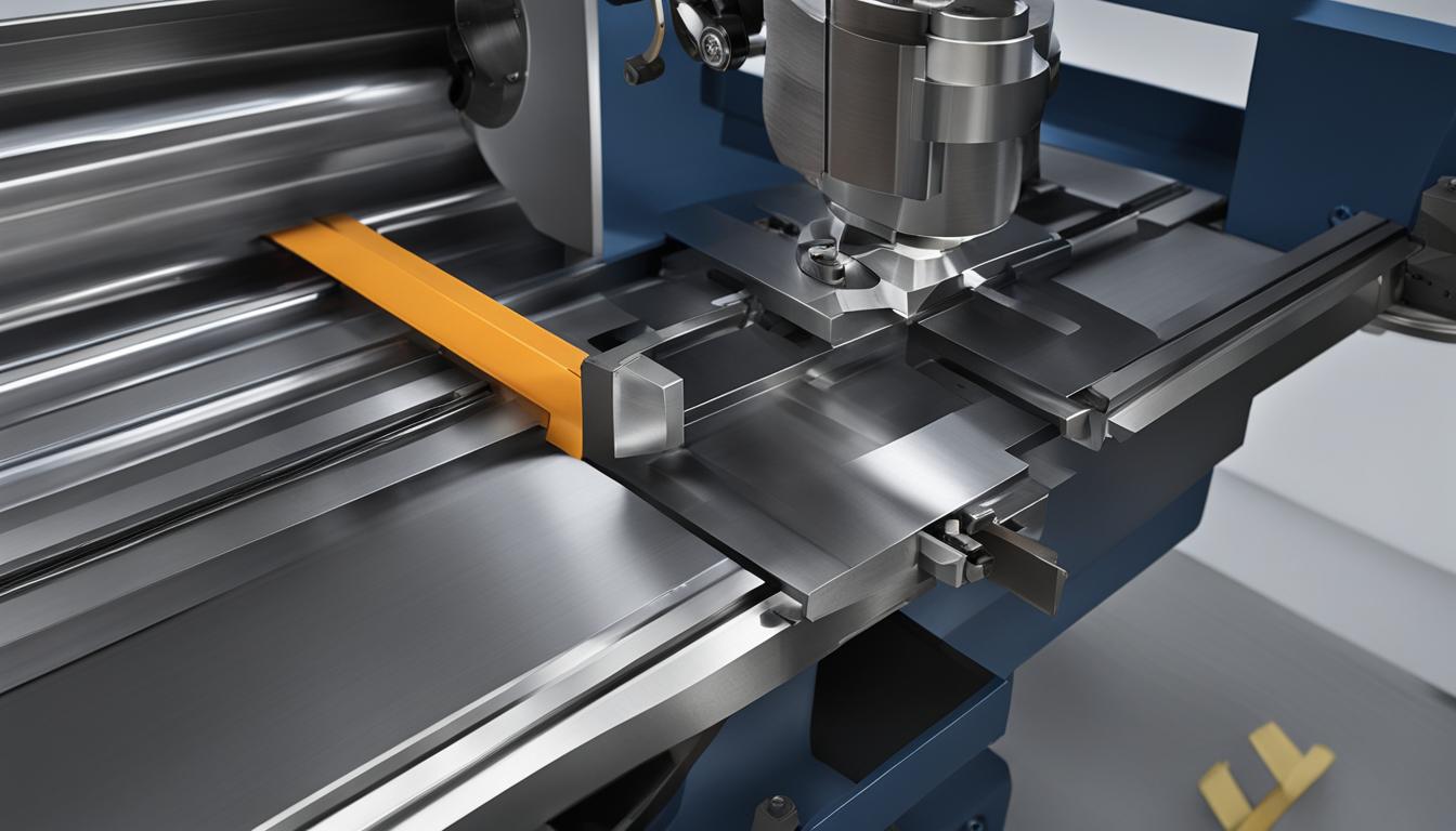
Lathes and shapers represent two foundational machine tools in subtractive manufacturing, each employing distinct kinematic principles to remove material. While both utilize single-point cutting tools, their operational mechanics dictate the types of geometries they can efficiently produce. Understanding these fundamental differences is crucial for selecting the appropriate process in precision engineering.
A primary distinction lies in the relative motion between the workpiece and the cutting tool, which profoundly influences the resulting part geometry and machining efficiency. This article delves into the technical disparities, from their core kinematics to practical applications and performance metrics.
Rotating Workpiece versus Reciprocating Linear Tool
Lathe machines operate on the principle of a rotating workpiece against a stationary, yet feedable, cutting tool. The workpiece is securely clamped in a chuck or between centers, rotating at a specified revolutions per minute (RPM) around its axis. This continuous rotation allows for the generation of axisymmetric forms.
Conversely, a shaper machine employs a reciprocating ram that moves a single-point cutting tool in a straight line across a stationary workpiece. The workpiece itself is rigidly clamped to a table, which can be indexed or fed incrementally perpendicular to the tool’s stroke. Material removal occurs only during the forward stroke of the ram.
Both machines typically utilize single-point cutting tools, but their presentation to the material differs significantly. The lathe’s tool engages continuously with the rotating part, while the shaper’s tool makes intermittent contact, cutting only during its forward motion.
Continuous Turned Shapes versus Flat Keyways
| Parameter | Lathe Machine | Shaper Machine |
|---|---|---|
| Primary Motion | Rotating Workpiece | Reciprocating Tool (Ram) |
| Workpiece State | Rotates | Stationary (with intermittent feed) |
| Tool State | Stationary (with feed) | Reciprocates |
| Typical Geometries | Cylindrical, Conical, Spherical, Threads | Flat, Angular, Keyways, Slots, Grooves |
| Cutting Action | Continuous | Intermittent (forward stroke only) |
| Material Removal Rate | Generally High | Generally Lower |
| Standard CNC Tolerances | ±0.005″ (±0.13 mm) to ±0.001″ (±0.025 mm) | Less precise than CNC milling/lathes for complex forms; good for small-scale flat work |
| Typical Surface Finish (Ra) | 125 µin (3.2 µm) to 8 µin (0.2 µm) | Dependent on setup, tool, and material; generally rougher than turned finishes |
| Modern Relevance | Widespread in CNC turning centers for mass production and precision | Niche applications, educational settings, prototyping, specific keyway cutting |
Lathes are inherently designed for producing cylindrical, conical, and spherical geometries. Operations such as turning, facing, boring, drilling, and threading are standard, creating parts like shafts, bushings, and pins. The continuous rotation of the workpiece ensures concentricity and uniform material removal around a central axis.
Shapers excel at generating flat, angular, and contoured surfaces, particularly useful for creating keyways, slots, and dovetail slides. The linear, reciprocating motion of the tool is ideal for machining internal splines and gear teeth, especially in smaller production runs.
While a lathe can produce complex profiles through contouring, these are always rotational. A shaper, however, is limited to linear cuts, making it unsuitable for generating cylindrical forms. This fundamental geometric capability defines their primary applications in manufacturing.
Machine Kinematics
The kinematics of a lathe involve the primary cutting motion derived from the workpiece’s rotation, coupled with the linear feed motion of the cutting tool. The tool moves along the workpiece’s axis (longitudinal feed) or perpendicular to it (cross feed), generating the desired profile. This coordinated movement allows for precise control over the final dimensions.
Shaper kinematics are characterized by the ram’s reciprocating motion, which carries the cutting tool. This linear motion is typically achieved through a ‘quick return mechanism,’ where the forward, cutting stroke is slower than the idle return stroke. This design optimizes the cutting cycle by minimizing non-productive time.
The workpiece on a shaper receives an intermittent cross-feed motion, usually at the end of each return stroke. This incremental movement positions new material for the next cutting pass, building up the desired flat or contoured surface. The depth of cut is adjusted by vertically moving the tool or the workpiece table.
Lathe Turning Efficiency versus Single-Stroke Shaping
Lathe turning offers high material removal rates due to its continuous cutting action. The tool is constantly engaged with the workpiece, leading to efficient chip formation and faster cycle times, especially for large production volumes of cylindrical parts. Modern CNC lathes further enhance this efficiency through optimized tool paths and rapid traverse rates.
Shapers, by contrast, are inherently less efficient in terms of material removal rate because cutting only occurs during the forward stroke. The return stroke is idle, representing non-productive time in the machining cycle. This intermittent cutting makes shapers generally slower than lathes or milling machines for bulk material removal.
Despite this, shapers remain valuable for specific tasks, particularly in small to medium-scale production or for creating features like keyways where their unique kinematics are advantageous. Their simplicity and lower tooling costs can make them a cost-effective solution for certain applications.
Technical Parameters and Modern Relevance
Modern CNC lathes can achieve impressive dimensional accuracy, with standard tolerances typically around ±0.005 inches (±0.13 mm) for most metals. For high-precision applications, tolerances can be tightened to ±0.001 inches (±0.025 mm) or even ±0.0005 inches (±0.0127 mm) on reamed holes. Specialized processes like grinding can push these limits to ±0.0001 inches (±0.0025 mm).
Surface finish on turned parts can range from 125 Ra for general machining to 32 Ra or better for precision surfaces, with superfinishing achieving as fine as 0.5 microinches (0.012 micrometers). Feeds and speeds vary significantly by material and tooling. For instance, turning aluminum with carbide tooling might use surface speeds of 600-1200 SFM, while mild steel could be 350-600 SFM.
Shaper cutting speeds typically range from 3 to 30 meters per minute (approximately 10 to 100 SFM), depending on the material. While not as precise as modern CNC milling or turning for complex geometries, shapers are accurate for small to medium-scale jobs requiring flat surfaces or keyways.
While CNC lathes dominate modern manufacturing for their versatility and precision, shapers retain a role in specific applications. Their ability to cut internal keyways and produce flat surfaces with relatively simple tooling ensures their continued, albeit specialized, use in tool rooms and educational environments.