
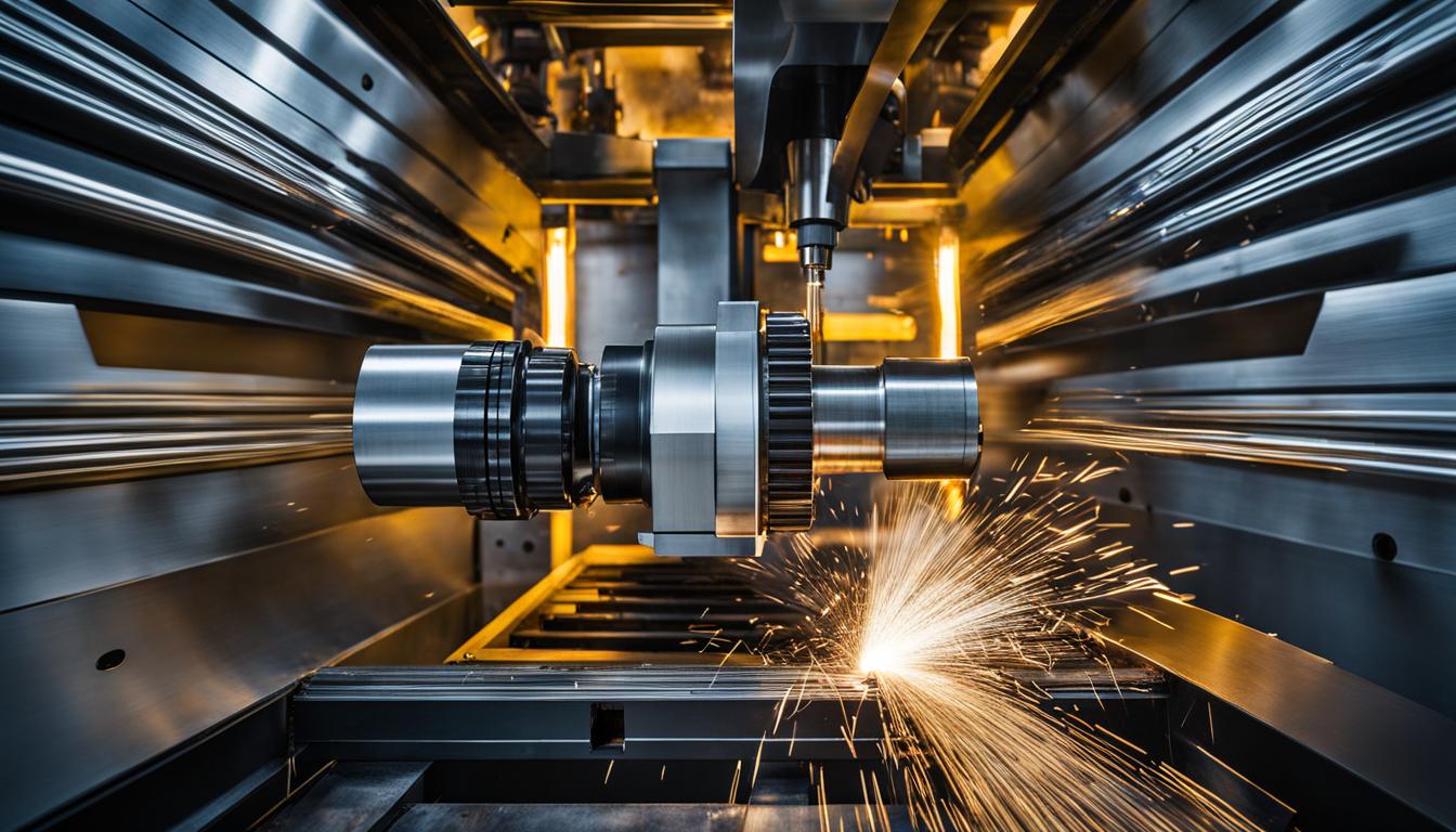
Computer Numerical Control (CNC) machines represent a fundamental shift in manufacturing, moving from manual operation to highly precise, automated processes. These systems interpret digital instructions to guide machining tools, ensuring exceptional consistency and accuracy in production. This automation significantly reduces human intervention, leading to increased efficiency and improved product quality across various industries.
The core principle of CNC involves a machine following a programmed set of commands to execute tasks like cutting, drilling, milling, or shaping materials. This digital control allows for intricate designs and complex geometries to be produced with remarkable repeatability.
Computer Numerical Control Principles
CNC systems operate on the principle of interpreting a machining program, typically G-code, to coordinate axis motion and manage various machine functions. The controller acts as the central brain, translating these digital instructions into physical movements.
These controllers can range from dedicated industrial hardware to PC-based systems, all designed to connect digital commands with the motors and mechanisms that drive the machine. They manage spindle speed, tool changes, and safety checks, ensuring a seamless manufacturing process.
Modern CNC machines often incorporate closed-loop control systems, especially with servo motors, where feedback mechanisms continuously monitor the motor’s actual position. This real-time monitoring allows for immediate adjustments, maintaining high precision and stability during machining operations. Stepper motors, while often open-loop, can also achieve high precision with proper drive parameter matching.
Digital Motor Driver Control
| Parameter | Standard CNC Machining | Precision CNC Machining |
|---|---|---|
| Linear Tolerance | ±0.127 mm (±0.005″) | ±0.0254 mm (±0.001″) |
| Angular Tolerance | ±0.5° | ±0.25° |
| 6061 Aluminum Roughing SFM (Carbide) | 800-1200 SFM (244-366 m/min) | N/A (Finishing values are higher) |
| 6061 Aluminum Finishing SFM (Carbide) | N/A (Roughing values are lower) | 1000-1500+ SFM (305-457+ m/min) |
Digital motor driver boards are crucial components in CNC systems, bridging the gap between the motion controller’s digital signals and the physical movement of the motors. They convert logic-level signals into electrical pulses that the motors understand, ensuring precise control and accurate execution of commands.
Stepper motors, commonly found in smaller CNC machines, operate by dividing a full rotation into discrete ‘steps.’ Their drivers energize motor coils in a specific sequence to achieve these precise movements. While cost-effective and simple, their torque can decrease at higher speeds.
Servo motors, conversely, are typically used in larger, high-precision CNC machines due to their ability to provide continuous rotation and maintain stable torque at high speeds. Their drivers work in conjunction with feedback mechanisms, such as encoders, to constantly monitor and adjust the motor’s position, ensuring high accuracy and responsiveness.
Selecting the appropriate motor and driver combination depends on the application’s specific requirements for speed, torque, and precision. Overheating, electrical noise, and motor stalling are common issues that can be mitigated with correct setup, thermal management, and compatibility with the motion controller and power supply.
G-Code Path Execution
G-code serves as the universal language for CNC machines, dictating specific actions like tool movement, feed rates, and spindle operations. The CNC controller interprets these commands, translating them into coordinated axis movements.
Linear interpolation, commanded by G01, moves the cutting tool in a straight line between two points at a specified feed rate. This is fundamental for creating straight edges and profiles. Rapid travel, designated by G00, moves the machine at its fastest possible speed without cutting, primarily for repositioning the tool.
Circular interpolation, using G02 for clockwise and G03 for counter-clockwise movements, enables the machine to cut along a circular arc. The controller calculates a series of very small straight steps that collectively form the curve. For full circles or arcs exceeding 180 degrees, ‘I’ and ‘J’ parameters, representing offsets from the arc’s start point to its center, are often used instead of a radius ‘R’ to avoid ambiguity.
More advanced interpolation methods, such as helical interpolation, combine circular motion with simultaneous linear movement along a third axis. This allows for the creation of threaded holes or spiral paths. Modern CAM software typically generates this complex G-code automatically, simplifying programming.
Subtractive Manufacturing Benefits
Subtractive manufacturing, the process of removing material from a raw workpiece to achieve a desired shape, offers numerous advantages in precision, surface finish, and material versatility. CNC machining is the predominant method for this process, ensuring high accuracy and repeatability.
This method excels in producing parts with superior surface finishes directly from the machine, often eliminating the need for extensive post-processing. It also provides high structural integrity, as parts are machined from solid blocks of material, unlike the layered composition of additive manufacturing.
Subtractive manufacturing is highly scalable for high-volume production of relatively simple to moderately complex parts. Once a process is optimized, CNC machines can produce thousands of identical components rapidly and consistently, leading to significant economies of scale.
The material selection for subtractive processes is extensive, encompassing metals, polymers, wood, and composites. This versatility makes it indispensable for applications requiring specific material properties and high durability.
CAD to CAM Pipeline
The CAD to CAM pipeline is a critical digital workflow that transforms a product design into machine-ready instructions. Computer-Aided Design (CAD) software is used to create detailed 3D models and technical drawings, defining the part’s geometry and specifications.
Following the design phase, Computer-Aided Manufacturing (CAM) software takes these CAD files and generates the necessary toolpaths and machining strategies. This involves determining the optimal cutting tools, speeds, feeds, and sequences of operations required to fabricate the part.
A seamless integration between CAD and CAM systems is vital for efficiency. This ‘digital continuity’ ensures that design changes in CAD are automatically reflected in CAM, minimizing errors and reducing the need for manual data transfer or re-programming.
Modern CAD/CAM solutions, such as Autodesk Fusion 360 or SolidWorks with SolidCAM, offer integrated environments that streamline this process, from design to toolpath simulation and post-processing. This integration significantly shortens programming and setup times, improving overall productivity and quality.
CNC Machining Tolerances and Feeds & Speeds
Achieving precision in CNC machining relies heavily on understanding and applying appropriate tolerances, which define the allowable deviation from nominal dimensions. Standard machining tolerances typically range from ±0.127 mm (±0.005″) to ±0.254 mm (±0.010″).
For applications demanding higher accuracy, precision machining services can achieve tolerances of ±0.0254 mm (±0.001″) to ±0.0508 mm (±0.002″). Industry leaders in tight tolerance CNC machining can even reach dimensional control at ±0.0025 mm (±0.0001″) or better, sometimes down to 1-3 microns for critical aerospace and medical components.
Optimal feeds and speeds are crucial for efficient material removal, tool life, and surface finish. These parameters, including surface feet per minute (SFM), chips per tooth (CPT), and feed rate (IPM), vary significantly based on the material, tool type, and operation. For 6061 aluminum with carbide end mills, recommended cutting speeds for roughing are typically 800-1200 SFM (244-366 m/min), and for finishing, 1000-1500+ SFM (305-457+ m/min).