
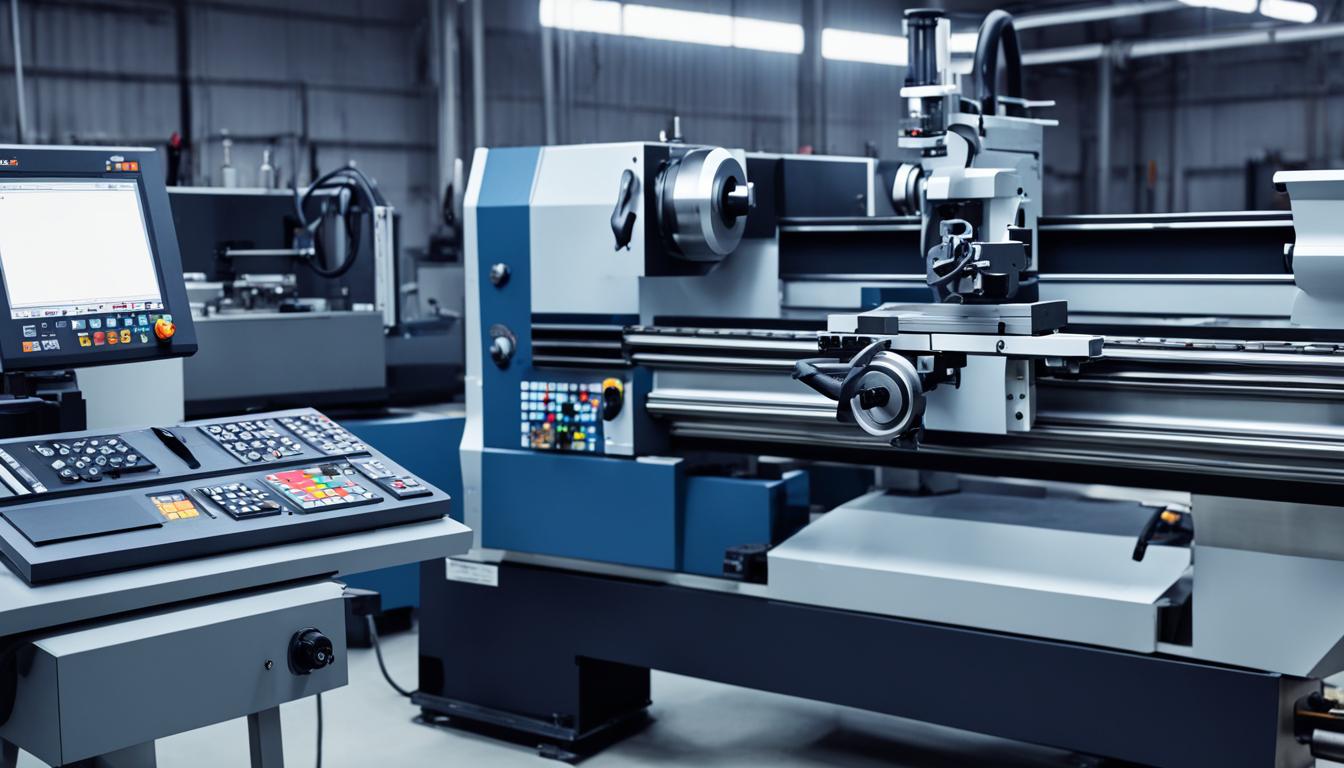
Understanding the distinction between a ‘CNC lathe’ and ‘CNC turning’ is fundamental for precision manufacturing professionals. A CNC lathe refers to the physical machine tool, a piece of hardware designed for specific machining operations. Conversely, CNC turning describes the subtractive manufacturing process itself, executed by such a machine.
This differentiation is crucial for proper terminology and comprehending the capabilities and applications within modern workshops. The machine provides the platform, while the process defines the material removal methodology.
Machine Hardware versus Process Operation
A CNC lathe is a computer numerically controlled machine tool primarily used for shaping workpieces by rotating them against a stationary cutting tool. These machines are robust, often featuring heavy cast iron bases for vibration dampening and precision. They integrate advanced control systems, servo motors, and feedback mechanisms to execute complex tool paths with high accuracy.
The machine’s structural components include the headstock, which houses the main spindle; the tailstock, providing support for longer workpieces; and the carriage, which moves the cutting tool along the X and Z axes. Modern CNC lathes can also incorporate Y-axis capabilities and live tooling for milling and drilling operations, expanding their versatility beyond traditional turning.
CNC turning, however, is the actual machining process where material is removed from a rotating workpiece to create a desired cylindrical or conical shape. This process involves a single-point cutting tool engaging the spinning material, progressively shaving away chips. The tool’s movement is precisely controlled by G-code instructions generated from CAD/CAM software.
This operation is highly efficient for producing parts with rotational symmetry, such as shafts, bushings, and intricate contours. The turning process encompasses various techniques like facing, tapering, grooving, threading, and boring, all performed by manipulating the cutting tool’s path relative to the rotating part.
Enclosed Turning Center Design and Function
| Parameter | General Machining | Precision Machining |
|---|---|---|
| Dimensional Tolerance (Diameter) | ±0.002 to ±0.005 inches (±0.05 to ±0.127 mm) | ±0.0005 to ±0.001 inches (±0.0127 to ±0.0254 mm) |
| Surface Finish (Ra) | 32 to 125 microinches (0.8 to 3.2 micrometers) | 8 to 32 microinches (0.2 to 0.8 micrometers) |
| Concentricity | 0.001 to 0.003 inches (0.025 to 0.076 mm) TIR | 0.0002 to 0.0005 inches (0.005 to 0.0127 mm) TIR |
| Typical Spindle Speed (Steel) | 200-800 RPM | 500-2000+ RPM |
| Typical Feed Rate (Steel) | 0.005-0.015 IPR (0.127-0.381 mm/rev) | 0.002-0.008 IPR (0.051-0.203 mm/rev) |
Modern CNC turning centers are almost universally enclosed, providing significant safety and operational benefits. These enclosures contain chips, coolant, and airborne particles, protecting operators from hazards. They also contribute to a cleaner shop environment by preventing the spread of machining byproducts.
Beyond safety, the enclosed design often integrates features like automatic door systems, chip conveyors, and high-pressure coolant delivery systems. These elements enhance automation, reduce manual intervention, and improve overall machining efficiency. The controlled environment also helps maintain thermal stability, which is critical for achieving tight tolerances.
Many turning centers feature advanced thermal compensation systems that actively monitor and adjust for temperature fluctuations within the machine structure. This proactive approach minimizes dimensional inaccuracies caused by thermal expansion or contraction during extended machining cycles. Such precision is vital for aerospace and medical component manufacturing.
Integrated part catchers and robotic loading/unloading systems are common in contemporary enclosed turning centers. These additions facilitate lights-out manufacturing, allowing machines to operate autonomously for extended periods, significantly boosting productivity and reducing labor costs.
Single-Point Cutting and Rotating Workpiece Mechanics
Single-point cutting is the defining characteristic of the turning process. A single cutting edge, typically made from carbide, ceramic, or CBN, removes material in a continuous chip. The geometry of this cutting edge, including its rake angle, relief angle, and nose radius, directly influences chip formation, surface finish, and tool life.
The cutting tool is rigidly mounted in a tool holder on a turret, which indexes to present different tools to the workpiece. The tool’s precise movement along the X (radial) and Z (axial) axes dictates the final part geometry. Advanced turning centers may also feature a Y-axis for off-center drilling or milling, and a B-axis for angular machining.
Workpiece mechanics in turning involve securely holding and rotating the material at a controlled speed. Chucks, typically three-jaw or four-jaw, are the most common workholding devices, gripping the workpiece externally or internally. Collets offer higher precision and gripping force for smaller diameter parts.
The headstock spindle, driven by a powerful motor, provides the rotational motion. Spindle speeds, measured in revolutions per minute (RPM), are critical and are calculated based on the material’s surface feet per minute (SFM) and the workpiece diameter. Maintaining consistent rotation is paramount for achieving uniform material removal and a quality surface finish.
Machine Classification Terminology in CNC
CNC lathes are broadly classified by their orientation and capabilities. Horizontal turning centers are the most common, with the spindle axis parallel to the floor, allowing chips to fall away easily. Vertical turning centers (VTLs) have a vertical spindle, ideal for machining large, heavy, or short workpieces that are difficult to chuck horizontally.
Further classifications include ‘chucker lathes,’ which process parts held only by a chuck, and ‘shaft lathes,’ which utilize both a chuck and a tailstock for longer components. ‘Swiss-type lathes’ are specialized machines where the workpiece moves axially past a stationary cutting tool, offering extreme precision for small, intricate parts.
The term ‘turning center’ often implies a CNC lathe with additional capabilities beyond basic turning. These can include live tooling for milling and drilling, Y-axis movement, sub-spindles for back-side machining, and automatic tool changers. These integrated features allow for complete part machining in a single setup, reducing cycle times and improving accuracy.
Multi-axis turning centers, such as 5-axis or 9-axis machines, combine turning with complex milling operations. These machines can perform highly intricate geometries, often eliminating the need for multiple setups across different machines. This integration streamlines production and enhances overall manufacturing flexibility.
Modern Engineering Practices and Parameters
Achieving optimal results in CNC turning requires careful consideration of feeds, speeds, and tooling. Feeds, measured in inches per revolution (IPR) or millimeters per revolution (mm/rev), dictate how fast the tool advances into the material. Speeds, expressed as surface feet per minute (SFM) or meters per minute (m/min), represent the cutting speed at the tool-workpiece interface.
Tooling selection is critical, with modern practices favoring indexable carbide inserts for their versatility and cost-effectiveness. Coatings like TiN, TiAlN, and AlTiN significantly extend tool life and improve performance across various materials. Chip breakers are also integral, designed to manage chip evacuation and prevent entanglement.
Standard tolerances for CNC turning vary significantly based on material, machine rigidity, and part geometry. General machining often targets tolerances of ±0.002 to ±0.005 inches (±0.05 to ±0.127 mm). Precision turning, however, can achieve much tighter tolerances, often down to ±0.0005 inches (±0.0127 mm) or even finer, especially with advanced machines and optimized processes.
Surface finish, measured in Ra (arithmetic average roughness), is another key parameter. Typical turned finishes range from 32 to 125 Ra microinches (0.8 to 3.2 Ra micrometers) for general applications. Fine turning can achieve 16 Ra microinches (0.4 Ra micrometers) or better, often requiring specific tool geometries, higher spindle speeds, and precise feed rates.