
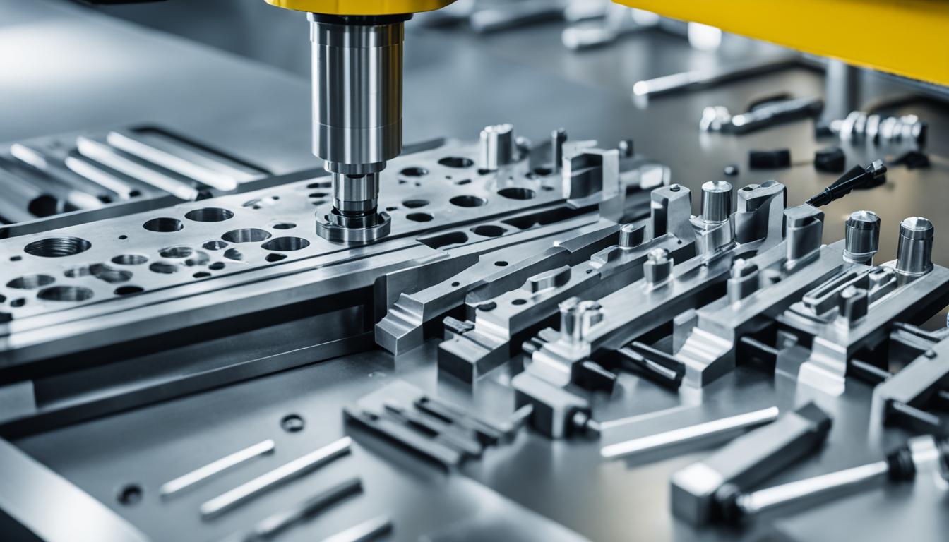
Achieving consistent, high-quality output from CNC machines requires more than just robust programming and capable machinery. Modern manufacturing demands a proactive, integrated approach to quality control, moving beyond post-process inspection to real-time monitoring and adjustment. Implementing advanced techniques ensures parts meet stringent specifications, minimizing scrap and maximizing efficiency.
Standard CNC machining tolerances typically range from ±0.05 mm to ±0.13 mm for most milling and turning operations. Achieving tighter tolerances, such as ±0.025 mm or even ±0.013 mm, necessitates specialized equipment, controlled environments, and advanced measurement capabilities.
Advanced Quality Control Techniques Ensure Perfect CNC Outputs
In-Process Spindle Touch Probing
In-process spindle touch probing integrates measurement directly into the CNC machining cycle, allowing for real-time data collection without removing the workpiece from the machine. This method significantly reduces setup times and enhances part accuracy by compensating for thermal expansion, fixture inaccuracies, and tool wear.
These probes, often featuring ruby sphere tips on carbon fiber styli, communicate wirelessly with the machine controller to capture precise X, Y, and Z coordinate data. Probing repeatability can be as low as 1 µm, though overall accuracy is influenced by factors like stylus length, probing force, and environmental conditions.
Common applications include automatic work offset setting, which establishes the coordinate system directly from the component’s datum features, and in-process feature measurement. This allows for verification of critical dimensions and geometric features, such as bore diameters or pocket depths, while the part is still clamped.
To ensure reliable readings, cleaning cycles are crucial before probing to remove chips, burrs, and coolant that could cause false measurements. Through-spindle air blasts or coolant flushes are often employed to clear the measurement area.
Coordinate Measuring Machines (CMM)
| Parameter | Description | Typical Application | Relationship to Ra (Approximate) |
|---|---|---|---|
| Ra (Arithmetic Average Roughness) | Arithmetic mean of the absolute departures of the roughness profile from the mean line. | General machining, cosmetic surfaces, most CNC jobs. | Baseline for comparison. |
| Rz (Mean Peak-to-Valley Height) | Average of the five largest peak-to-valley heights within sampling lengths. | Hydraulic fittings, sealing surfaces, fatigue-sensitive parts. | Rz is typically 4-10 times larger than Ra. |
| Rq (Root Mean Square Roughness) | Root mean square value of the profile deviations from the mean line. | Optics, semiconductor applications, where larger deviations are critical. | Rq is always slightly higher than Ra (approx. 1.11 to 1.25 times Ra). |
Coordinate Measuring Machines (CMMs) remain a cornerstone of precision metrology, providing highly accurate dimensional and geometric measurements of finished parts. Modern CMMs are increasingly integrated into CNC machining cells for real-time, in-process inspection, reducing delays and rework.
CMM accuracy is typically expressed as a measurement uncertainty, often in the range of a few microns. For example, a typical bridge CMM in a temperature-controlled environment might have a Maximum Permissible Error (MPE) of ±(3.0 + L/250) µm, where L is the measured length in millimeters.
Factors influencing CMM accuracy include the quality of the probe or sensor, the stability of mechanical components, and environmental conditions like temperature and humidity. Regular calibration, typically to ISO 10360 standards, is essential to verify and maintain accuracy.
Recent advancements in CMM technology include multi-sensor platforms that combine tactile probing with laser scanners, optical vision systems, and white-light sensors. This expands measurement capabilities for complex geometries and supports predictive quality management through AI and data analytics.
Laser Tool Setters
Laser tool setters provide non-contact, high-speed measurement and broken tool detection directly within the CNC machine. These systems are critical for maintaining dimensional accuracy and part quality by addressing issues like tool wear, run-out, and breakage during the machining process.
Operating by detecting the interruption of a laser beam as a tool passes through it, these systems offer sub-micron accuracy and are particularly beneficial for small or delicate tools that could be damaged by contact methods. They enable tools to be measured at normal spindle speeds, accounting for dynamic run-out.
Key benefits include faster tool setting cycles, reduced need for rework, enhanced overall productivity, and significant cost savings. Advanced systems, such as Renishaw’s NC4+ Blue, achieve repeatability as low as ±0.1 µm and can detect tool defects as small as 5 microns.
Laser tool setters also play a vital role in enabling ‘lights-out’ manufacturing by providing automated tool wear compensation and cutter integrity checks. Integrated protection systems, including mechanical shutters and air barriers, ensure reliable performance even in harsh machine environments.
Statistical Process Control (SPC)
Statistical Process Control (SPC) is a crucial quality management tool that monitors and improves product quality during the production process by tracking real-time data. It helps identify anomalies and implement corrective measures, enhancing the stability of CNC machined parts.
SPC relies on control charts, which are visual tools displaying the variation of key variables over time. Common types include X-bar (mean) and R (range) charts for variable data, and P or C charts for attribute data. These charts help distinguish between common cause variation (natural fluctuations) and special cause variation (unusual deviations requiring action).
Implementing SPC involves collecting data on process parameters like tool wear, cutting speed, feed rate, and dimensional accuracy. This data is then plotted on control charts with upper and lower control limits, typically set at ±3 standard deviations from the process average.
When data points fall outside these control limits or exhibit specific trends, it signals an out-of-control condition, prompting investigation and analysis to identify root causes. Modern SPC is often enhanced by software solutions that automate chart plotting, flag deviations, and integrate with ERP systems for real-time monitoring.
SPC helps predict and prevent defects before they exceed tolerance limits, leading to reduced scrap rates and improved product consistency. It is a continuous improvement tool, with control limits and improvement measures adjusted based on real-world conditions.
Surface Finish Roughness Gauges
Surface finish roughness gauges are essential instruments for quantifying micro-level irregularities on a material’s surface, which significantly impact part performance, longevity, and aesthetics. These devices ensure components meet specified surface texture requirements.
There are two primary types of surface finish measuring systems: ‘skidded’ gauges, which measure roughness only using the workpiece as a reference, and ‘skidless’ gauges, which use an internal precision reference to evaluate form, waviness, and roughness.
Key surface roughness parameters include Ra (Arithmetic Average Roughness), Rz (Mean Peak-to-Valley Height), and Rq (Root Mean Square Roughness). Ra is the most commonly specified and universally recognized parameter, representing the average of absolute deviations from the mean line.
Rz, in contrast, captures the worst-case peak-to-valley height, making it critical for applications requiring sealing or fatigue resistance. It is calculated by averaging the five largest peak-to-valley heights across sampling lengths. Rq, similar to Ra, weights larger deviations more heavily and is often used in optics and semiconductor applications.
International standards such as ISO 21920, ISO 25178, and ASME B46.1 ensure consistent and traceable roughness measurement. For critical components, specifying multiple parameters provides a more comprehensive understanding of surface quality than any single value alone.