
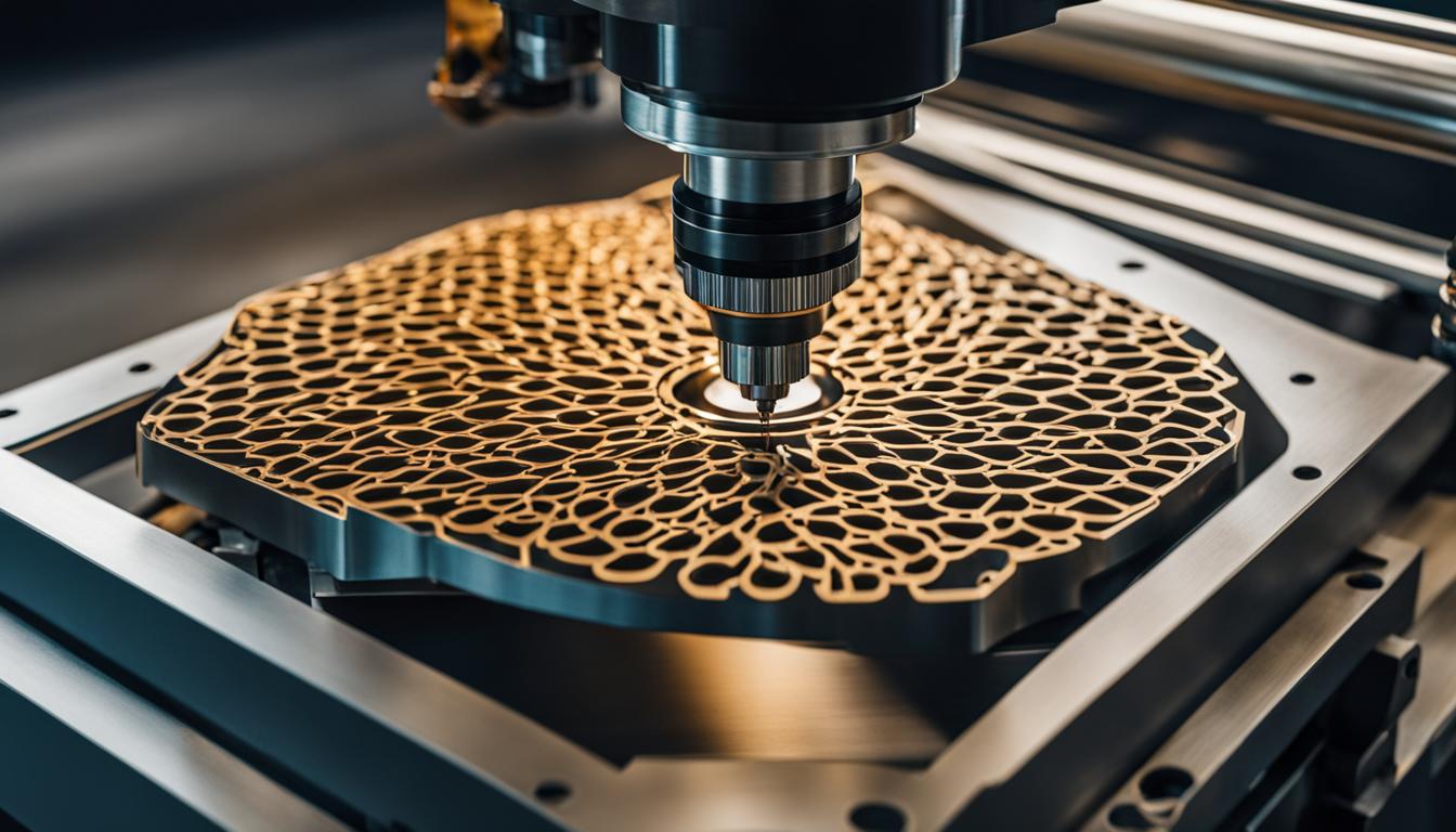
Computer Numerical Control (CNC) machining has fundamentally transformed rapid prototyping, moving beyond its traditional role to become an indispensable tool for accelerating product development. Modern CNC systems offer unparalleled precision, speed, and versatility, enabling engineers to quickly iterate and validate designs with high-fidelity physical parts.
Accelerating Prototyping with Dynamic Milling
High-efficiency dynamic milling (HEM) represents a significant advancement in CNC machining strategies, particularly for rapid prototyping. This technique, often referred to as adaptive clearing, maintains a consistent chip load and tool engagement angle throughout the cut, optimizing material removal rates (MRR) and extending tool life. It contrasts sharply with conventional milling, which can lead to inconsistent loads and premature tool wear.
HEM toolpaths, such as trochoidal milling, utilize a smaller radial depth of cut (RDOC) but a larger axial depth of cut (ADOC). This approach distributes cutting forces more evenly along the entire flute length of the tool, preventing localized wear and heat buildup. The result is a smoother, faster machining process with reduced stress on both the tool and the machine.
Optimizing feeds and speeds is critical for dynamic milling. For aluminum, cutting speeds can range from 300 to 600 meters per minute, with feed rates typically between 0.1 and 0.3 millimeters per tooth. Steel, being harder, requires slower cutting speeds, generally from 50 to 150 meters per minute. Effective chip evacuation, often aided by high-pressure coolant or air blast, is paramount to prevent chip recutting and maintain tool performance.
Modern carbide end mills, featuring specialized geometries like high positive rake angles and polished flutes, are engineered to excel in dynamic milling applications. These tools are designed to minimize built-up edge and facilitate efficient chip flow, which is crucial for maintaining consistent cutting action and surface finish.
Unlocking Complexity with Multi-Axis Rapid Machining
| Parameter | Traditional Milling (Roughing) | High-Efficiency Dynamic Milling (Roughing) |
|---|---|---|
| Cutting Speed (Vc) | 150-250 m/min (500-800 SFM) | 300-600 m/min (1000-2000 SFM) |
| Feed Rate (fz) | 0.08-0.15 mm/tooth (0.003-0.006 IPT) | 0.1-0.3 mm/tooth (0.004-0.012 IPT) |
| Axial Depth of Cut (ADOC) | 0.5-1.0 x Tool Diameter | 1.0-2.0 x Tool Diameter (or more) |
| Radial Depth of Cut (RDOC) | 0.5-1.0 x Tool Diameter | 0.05-0.15 x Tool Diameter (5-15% of tool diameter) |
| Material Removal Rate (MRR) | Moderate | High (often 2-3x traditional) |
| Tool Life | Standard | Extended due to even wear |
Multi-axis machining, encompassing both 3+2 positional and simultaneous 5-axis capabilities, is pivotal for rapid prototyping of intricate components. This technology allows for machining on multiple faces of a workpiece in a single setup, significantly reducing cumulative errors from re-fixturing and shortening overall lead times. It enables the creation of complex geometries and curved surfaces that are challenging or impossible with traditional 3-axis methods.
A key advantage of multi-axis machining is the ability to use shorter, more rigid cutting tools. This reduces tool deflection and vibration, leading to superior surface finishes directly from the machine and often eliminating the need for extensive post-processing operations like deburring or polishing.
Precision is a hallmark of modern multi-axis CNC machines. They can reliably achieve tight tolerances, typically around ±0.025 mm (±0.001 in) for standard precision work, with high-precision operations reaching up to ±0.01 mm under controlled conditions. Angular tolerances are commonly held within ±0.25° for demanding applications.
Industries such as aerospace and medical device manufacturing heavily leverage multi-axis prototyping. Components like turbine blades, orthopedic implants, and complex mold cavities, which feature organic shapes and deep undercuts, benefit immensely from the capabilities of 5-axis machining.
Intelligent Design and Setup Optimization
Automated Design for Manufacturability (DFM) feedback systems are transforming the initial stages of rapid prototyping. These software tools integrate directly with CAD/CAM platforms, providing real-time analysis of a design’s manufacturability as it is being created. This proactive approach identifies potential production issues before they become costly problems on the shop floor.
The benefits of automated DFM are substantial, including reduced design iterations, lower manufacturing costs, and accelerated time-to-market. The system flags common issues such as thin walls, deep pockets requiring specialized tooling, or features that are inaccessible to standard cutting tools, often suggesting immediate design optimizations.
Complementing DFM, quick-change modular fixturing systems significantly streamline the physical setup process. These systems utilize standardized, reusable components like grid plates, clamps, stops, and risers that can be rapidly assembled and disassembled to secure workpieces. This ‘building block’ approach replaces the need for custom, dedicated fixtures for every new part.
Operational efficiency gains are considerable, with setup times drastically reduced and machine utilization increased. Zero-point clamping systems, a core element of modular fixturing, provide exceptional repeatability, often within 5 microns, ensuring consistent workpiece positioning across multiple setups or repeat jobs. This allows for offline setup, where the next job’s fixture can be prepared while the machine is still running, further minimizing downtime.
Seamless Transition: Direct CAD-To-Part Workflow
The direct CAD-to-part workflow represents a unified approach to manufacturing, where design data flows seamlessly from Computer-Aided Design (CAD) to Computer-Aided Manufacturing (CAM) and directly to the CNC machine. This integration eliminates the need for manual data translation and conversion, which historically introduced errors and delays in the prototyping process.
Integrated CAD/CAM platforms, such as Autodesk Fusion 360 or Mastercam, are central to this workflow. These systems allow designers to create complex 3D models and then generate optimized toolpaths for CNC machining within the same software environment. This fosters concurrent engineering, where design and manufacturing considerations are addressed simultaneously.
This streamlined process significantly impacts efficiency, leading to faster iteration cycles and reduced material waste. By maintaining a single source of truth for the part geometry, the risk of misinterpretation or outdated revisions is virtually eliminated, ensuring higher accuracy and consistency in the manufactured prototype.
Advanced post-processors and the concept of a ‘digital twin’ further enhance this workflow, ensuring that the machine precisely executes the CAM instructions. This robust connection between the virtual design and the physical manufacturing process is fundamental to achieving rapid, high-quality prototypes in modern engineering.