
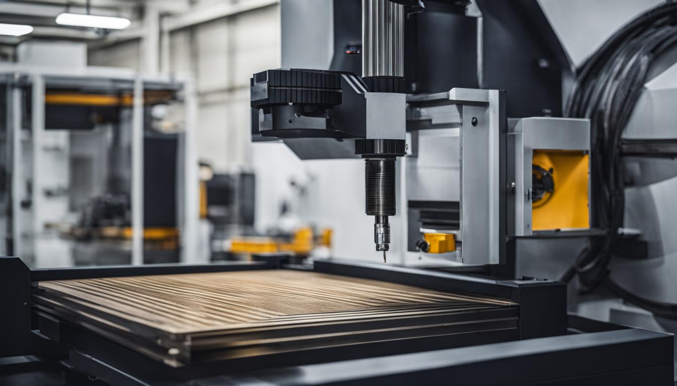
Computer Numerical Control (CNC) machines rely on a precise language to execute complex manufacturing operations. This language is primarily composed of G-codes and M-codes, which serve distinct but complementary roles in directing machine behavior. Understanding their fundamental differences is critical for any tooling engineer or machinist aiming for optimal program efficiency and part accuracy.
G-codes, often referred to as ‘Geometric codes’ or ‘preparatory functions,’ primarily dictate the cutting tool’s movement and the geometric path it follows. These commands define where the tool moves, how fast it travels, and the specific trajectory it takes across the workpiece.
G-Codes Direct Toolpath Movement
G-codes are the backbone of toolpath generation, instructing the CNC controller on the precise coordinates and motion types required for material removal. They are responsible for all aspects of tool positioning and movement, from rapid traverses to controlled cutting feeds.
A common G-code, G00, commands the machine to move the tool at its fastest possible speed to a specified location without cutting, typically used for non-machining movements. Conversely, G01 initiates linear interpolation, moving the tool in a straight line at a programmed feed rate, which is essential for cutting operations.
These codes are modal, meaning once a G-code is activated, it remains in effect for subsequent blocks of code until another G-code from the same group cancels or overrides it. For instance, a G01 command will keep the machine in linear feed mode until a G00, G02, or G03 is encountered.
M-Codes Govern Auxiliary Machine Operations
| Code Type | Function | Common Examples | Modality |
|---|---|---|---|
| G-Code | Tool Motion & Geometry | G00 (Rapid Traverse), G01 (Linear Interpolation), G02/G03 (Circular Interpolation), G90/G91 (Absolute/Incremental Positioning) | Mostly Modal |
| M-Code | Machine Functions | M03/M04 (Spindle On CW/CCW), M05 (Spindle Stop), M06 (Tool Change), M08/M09 (Coolant On/Off), M30 (Program End & Reset) | Often Non-Modal, Machine-Specific |
M-codes, or ‘Miscellaneous codes,’ manage the auxiliary functions of a CNC machine that are not directly related to tool motion. These commands control the machine’s physical actions and environmental conditions, ensuring the machining process runs safely and efficiently.
Examples of M-code functions include activating and deactivating the spindle, controlling coolant flow, initiating tool changes, and managing program stops. They essentially ‘flip switches’ on the machine, preparing it for or reacting to the tool’s geometric movements.
Unlike many G-codes, M-codes are often machine-specific and can vary significantly between different CNC manufacturers and control systems, such as Fanuc, Haas, or Siemens. Consulting the machine’s specific manual is crucial for accurate M-code implementation.
Interpolation and Advanced G-Code Functions
Beyond simple linear movements, G-codes enable complex toolpaths through interpolation. Circular interpolation, commanded by G02 for clockwise and G03 for counter-clockwise arcs, allows the machine to cut curved features like radii, fillets, and holes.
These circular commands require defining the arc’s endpoint coordinates and either the center of the arc using ‘I’, ‘J’, ‘K’ parameters (for X, Y, Z axes respectively) or a radius value using ‘R’. The choice between ‘IJK’ and ‘R’ depends on the arc’s complexity and the programmer’s preference.
Other critical G-codes include G17, G18, and G19 for plane selection (XY, XZ, YZ respectively), which is vital for multi-axis machining and defining the plane for circular interpolation. G90 and G91 switch between absolute and incremental positioning modes, fundamentally altering how coordinate values are interpreted.
Spindle, Coolant, and Tool Change M-Codes
M-codes are indispensable for managing the operational environment of the machining process. Spindle control is handled by M03 (spindle start clockwise), M04 (spindle start counter-clockwise), and M05 (spindle stop). These are typically paired with an ‘S’ word to define the spindle speed in RPM.
Coolant management is another primary function of M-codes. M08 activates flood coolant, while M07 may activate mist coolant on some machines. M09 universally turns off all active coolant systems.
The M06 command initiates an automatic tool change, a complex sequence involving stopping the spindle, moving the Z-axis to a safe position, and exchanging the tool. M30 signals the end of the program and resets the controller to the beginning, preparing for the next cycle.
CNC Controller Parsing and Execution Logic
CNC controllers process G-codes and M-codes sequentially within the same program file, executing each instruction in order. While G-codes define the ‘what’ and ‘where’ of tool movement, M-codes dictate the ‘how’ and ‘when’ of machine actions surrounding that movement.
The controller reads an entire block of code, sets the states for each command, and then performs the actions based on the new machine state. For instance, an M03 (spindle start) command must precede a G01 (linear interpolation) cutting move to ensure the spindle is rotating before the tool engages the workpiece.
Modern CAM software typically generates both G-codes and M-codes, translating design intent into machine-specific instructions via post-processors. However, understanding the parsing rules and potential variations between controllers is crucial for debugging and optimizing programs.
Practical G-Code and M-Code Syntax Examples
CNC programs combine G-codes, M-codes, and other parameters like feed rate (‘F’), spindle speed (‘S’), and tool number (‘T’) within individual blocks or lines of code. Each block represents a distinct step in the machining process.
Consider a common sequence: ‘N10 G90 G54 G00 X10.0 Y10.0 Z5.0’. This block sets absolute positioning (G90), selects work offset 1 (G54), and rapidly positions the tool to X10.0, Y10.0, and Z5.0.
Following this, ‘N20 S1500 M03’ would start the spindle clockwise at 1500 RPM. Then, ‘N30 G01 Z-2.0 F10.0 M08’ would linearly interpolate down to Z-2.0 at a feed rate of 10 units per minute, simultaneously turning on flood coolant.