
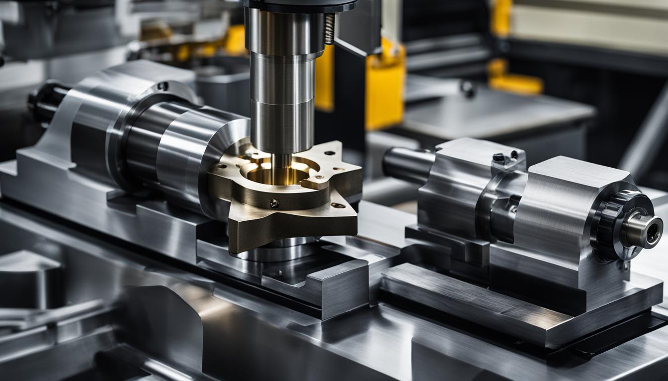
Machining centers and turning centers represent two fundamental pillars of subtractive manufacturing, each optimized for specific part geometries and production methodologies. While both utilize Computer Numerical Control (CNC) for automated precision, their core operational principles diverge significantly. Understanding these distinctions is critical for engineers selecting the appropriate equipment for a given manufacturing task.
A machining center, often referred to as a CNC mill, employs a rotating cutting tool to remove material from a workpiece that is typically held stationary. This setup is ideal for creating complex, prismatic components with features like slots, holes, and intricate contours across multiple faces.
Conversely, a turning center, or CNC lathe, operates by rotating the workpiece at high speeds while a stationary or linearly moving cutting tool shapes it. This method excels at producing cylindrical, conical, and spherical parts, such as shafts, bushings, and flanges, with exceptional concentricity.
Fundamental Operational Principles
The primary difference between these machine types lies in the motion of the cutting action. Machining centers, including Vertical Machining Centers (VMCs) and Horizontal Machining Centers (HMCs), rely on a rotary tool, such as an end mill or drill, to perform material removal. The workpiece remains fixed on a table, allowing the tool to traverse its surfaces in multiple directions.
Turning centers, however, fundamentally operate with a rotary part. The workpiece is securely clamped in a chuck or collet and rotates around its central axis. A non-rotating cutting tool, typically an insert, then engages the spinning material to generate the desired cylindrical form.
This distinction dictates the types of operations each machine performs most efficiently. Machining centers are adept at milling, drilling, boring, and tapping, creating features that lack rotational symmetry. Turning centers specialize in operations like turning, facing, boring, threading, and grooving, all centered around the workpiece’s axis of rotation.
Axis Configurations and Kinematics
| Feature | Machining Center (Milling Focus) | Turning Center (Lathe Focus) |
|---|---|---|
| Primary Motion | Rotating tool, stationary workpiece | Rotating workpiece, stationary tool |
| Typical Axes | 3-5 linear axes (X, Y, Z, A, B/C) | 2-3 lathe axes (X, Z, C, sometimes Y) |
| Part Geometry Focus | Prismatic, complex contours, multi-face features | Cylindrical, conical, spherical, rotational symmetry |
| Tooling Type | Rotary tools (end mills, drills, taps) | Stationary inserts (turning, boring, grooving tools) |
| Workholding | Vices, clamps, custom fixtures on a table | Chucks, collets, steady rests on a spindle |
| Common Applications | Engine blocks, molds, brackets, housings | Shafts, pins, bushings, hydraulic fittings |
Machining centers typically feature 3 to 5 linear axes, providing extensive flexibility for complex geometries. A standard 3-axis machine controls movement along the X (left-right), Y (front-back), and Z (up-down) axes. This configuration is suitable for machining on a single plane or simple 3D contours.
More advanced machining centers incorporate additional rotary axes, such as A (rotation around X), B (rotation around Y), and C (rotation around Z). A 5-axis machine, for instance, allows simultaneous movement along five axes, enabling the cutting tool to approach the workpiece from virtually any angle. This capability is crucial for intricate surfaces, undercuts, and machining multiple faces in a single setup, significantly reducing repositioning and potential errors.
Turning centers traditionally operate with 2 axes (X and Z), controlling the radial and longitudinal movement of the cutting tool relative to the rotating workpiece. The X-axis manages the diameter, while the Z-axis controls the length. Modern turning centers often include a C-axis for controlled spindle rotation, allowing for indexing and the integration of ‘live tooling’.
The addition of a Y-axis on some turning centers further expands their capabilities, enabling off-center drilling and milling operations. These multi-axis turning centers, often called ‘turn-mill’ machines, blur the lines between traditional turning and milling, allowing for highly complex parts to be completed in a single setup.
Tooling and Workholding Strategies
Tooling for machining centers primarily consists of rotary cutting tools, including end mills, face mills, drills, taps, and reamers. These tools are held in an automatic tool changer (ATC) system, which can store a large number of tools (20 to 60 or more) and automatically swap them as programmed. Workholding typically involves vices, clamps, or custom fixtures that rigidly secure the stationary workpiece to the machine table.
Turning centers utilize stationary cutting tools, predominantly indexable inserts mounted on boring bars, turning tools, or grooving tools. These tools are typically housed in a turret, which can quickly index to present the required tool to the workpiece. Workholding on a turning center is achieved through a chuck or collet, which grips the workpiece and rotates it.
The choice of tooling and workholding directly impacts efficiency and part quality. Machining centers benefit from the versatility of numerous rotary tools for multi-face operations, while turning centers leverage the speed and precision of fixed tools for concentric features. The integration of live tooling on turning centers allows for some milling and drilling, bridging the gap between the two machine types.
Part Geometry and Application Suitability
Machining centers are inherently suited for prismatic parts, which are characterized by flat surfaces, pockets, slots, and holes on various faces. Industries such as aerospace, automotive, and mold making heavily rely on machining centers for components like engine blocks, brackets, and complex molds.
Turning centers excel at producing rotationally symmetric components. This includes shafts, pins, bushings, and hydraulic fittings, where concentricity and diametral accuracy are paramount. Their efficiency in creating round parts makes them indispensable for high-volume production of such geometries.
The emergence of multi-tasking machines, often referred to as ‘turn-mill’ centers, combines the capabilities of both. These machines can perform both turning and milling operations in a single setup, reducing part handling and improving accuracy for complex parts that require both rotational and prismatic features.
Precision, Tolerances, and Surface Finish
Both machining and turning centers are capable of achieving high precision, though the nature of their inherent strengths differs. Standard CNC machining tolerances typically range from ±0.005 inches (±0.127 mm) for most metals. However, precision machining operations can achieve tighter tolerances of ±0.001 inches (±0.025 mm) or better.
Turning centers generally excel at maintaining concentricity and diametral accuracy due to the part’s rotation on its centerline. They can routinely hold turned tolerances to ±0.0003 inches (±0.0076 mm) and sometimes even ±0.0002 inches (±0.0051 mm) on various materials. This continuous cutting action often results in smoother cylindrical and internal hole surfaces.
Machining centers achieve precision through the accuracy of their linear axes, ball screws, and control compensation. Milled positional tolerances can be held to ±0.0005 inches (±0.0127 mm) on adjacent features and ±0.001 inches (±0.0254 mm) on non-adjacent or datum-oriented features. Achieving high precision on non-axis-aligned features requires exceptional machine rigidity.
Typical CNC-machined surfaces can range from fine finishes below 1 µm Ra to rougher surfaces around 6.3–12.5 µm Ra, depending on the process, tooling, and material. Turning often produces superior surface finishes on cylindrical features due to the continuous cutting action, while milling may require additional finishing passes to achieve comparable smoothness.
Feeds, Speeds, and Modern Practices
Optimizing feeds and speeds is crucial for efficient material removal, tool life, and surface finish in both machining and turning. For milling aluminum, recommended spindle RPM often falls between 8,000–12,000, with feed rates of 40–80 inches per minute (IPM) for a 2-flute end mill. Mild steel typically requires lower RPMs, around 6,000–9,000, and slower feed rates of 20–40 IPM.
Turning aluminum commonly uses surface speeds of 600 to 1200 surface feet per minute (SFM) with carbide tooling. Feed rates for roughing passes can be 0.004 to 0.010 inches per revolution (IPR), while finishing passes might use 0.002 to 0.005 IPR for a finer surface. For steel, cutting speeds are generally lower, ranging from 80-150 meters per minute (approximately 260-490 SFM).
Modern engineering practices in CNC machining are increasingly focused on automation, artificial intelligence (AI), and machine learning. AI algorithms optimize tool paths, predict maintenance needs, and monitor quality in real-time, enhancing efficiency and reliability. Robotics are also integrated for tasks like material loading, unloading, and inspection, enabling 24/7 operation and reducing human error.