
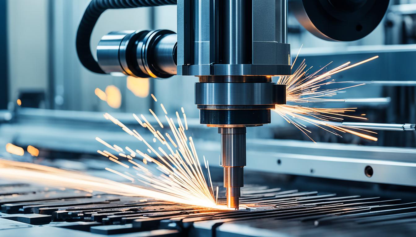
Computer Numerical Control (CNC) cutting involves the precise removal of material from a workpiece to achieve a desired geometry. This subtractive manufacturing process relies on programmed instructions to guide cutting tools, shaping raw stock into finished components with high accuracy and repeatability. The fundamental principles govern how material is efficiently and effectively removed.
Understanding Subtractive Machining Fundamentals
Subtractive manufacturing, at its core, is the process of removing unwanted material from a solid block or workpiece to create a final part. This method contrasts with additive processes, which build up material layer by layer. CNC machining utilizes various cutting tools to shear, abrade, or erode material, producing chips as a byproduct.
Material removal occurs when the cutting tool’s edge exerts sufficient force to overcome the material’s shear strength, causing a small segment to deform and separate as a chip. The efficiency of this process is influenced by factors such as tool geometry, workpiece material properties, and the machine’s rigidity. Effective chip evacuation is critical to prevent re-cutting and heat buildup, which can degrade tool life and part quality.
The interaction between the cutting tool and the workpiece generates significant heat and forces. Proper coolant application helps dissipate this heat, lubricate the cutting zone, and flush chips away. Understanding these dynamics is essential for preventing tool wear, maintaining dimensional accuracy, and achieving desired surface finishes.
Strategic Tool Selection for Diverse Materials
| Material Type | Recommended Tool Material | Typical Coating | Key Tool Geometry |
|---|---|---|---|
| Aluminum Alloys | Carbide, HSS | TiN, ZrN, uncoated | Sharp edge, high rake, polished flutes |
| Stainless Steel | Carbide | AlTiN, TiAlN | Strong edge, variable helix |
| Tool Steel (Hardened) | Solid Carbide | AlTiN, TiSiN | High helix, robust core |
| Engineering Plastics | Carbide, HSS | Uncoated, DLC | Sharp edge, high rake, single/two flute |
| Titanium Alloys | Solid Carbide | AlTiN, TiAlN | Strong edge, specific helix, coolant-through |
Selecting the correct cutting tool is paramount for efficient and high-quality CNC machining across various materials. Tool material, geometry, and coating must be matched to the workpiece’s hardness, abrasiveness, and thermal properties. High-speed steel (HSS) tools are economical for softer materials and lower speeds, offering good toughness.
Carbide tools, composed of tungsten carbide particles bonded with cobalt, offer superior hardness and heat resistance, making them ideal for machining harder materials at higher speeds. Modern carbide tools often feature advanced coatings like TiN, TiAlN, AlTiN, or DLC, which further enhance hardness, lubricity, and wear resistance, extending tool life significantly.
For machining aluminum and other non-ferrous metals, tools with sharper cutting edges, higher rake angles, and polished flutes are preferred to prevent material adhesion and promote efficient chip evacuation. Conversely, tougher materials like stainless steel or titanium require tools with stronger edge geometries, often with specialized coatings, to withstand higher cutting forces and temperatures.
Engineering plastics, such as Delrin (POM) or PEEK, benefit from sharp, single-flute or two-flute end mills designed to minimize heat generation and prevent melting or gumming. The specific application, including roughing versus finishing operations, also dictates tool choice, with roughing tools designed for aggressive material removal and finishing tools optimized for surface quality.
Mastering Feeds and Speeds Calculations
Accurate calculation of feeds and speeds is fundamental to optimizing machining performance, tool life, and part quality. Surface Feet Per Minute (SFM) or Surface Meters Per Minute (SMM) represents the speed at which the cutting edge passes over the material. This value is crucial for determining the spindle Revolutions Per Minute (RPM).
The formula for RPM is: RPM = (SFM × 3.82) / Tool Diameter (inches). For example, machining 6061 aluminum with a 0.5-inch end mill might use an SFM of 800-1200. This translates to an RPM range of approximately 6000-9168 for a 0.5-inch tool.
Feed rate, or Inches Per Minute (IPM), dictates how fast the tool moves through the material. It is calculated using the formula: IPM = RPM × Number of Flutes × Chip Load (IPT). Chip Load, or Inches Per Tooth (IPT), is the amount of material each tooth removes per revolution and is a critical factor in chip formation and tool wear. Typical chip loads for aluminum can range from 0.002 to 0.006 inches per tooth for a 0.5-inch end mill.
Adjusting feeds and speeds based on material hardness, tool rigidity, machine power, and desired surface finish is essential. Too high a feed rate can lead to tool breakage or poor finish, while too low can cause rubbing, excessive heat, and premature tool wear. Modern CAM software often provides initial recommendations, but fine-tuning is often necessary based on real-world conditions.
Ensuring Workholding Stability and Rigidity
Workholding stability is a non-negotiable aspect of precision CNC machining. Any movement or vibration of the workpiece during cutting directly translates to inaccuracies, poor surface finish, and potential tool damage. The primary goal of workholding is to securely clamp the part, resisting all cutting forces without deforming the workpiece.
Common workholding methods include vises, clamps, chucks, and custom fixtures. Vises are versatile for prismatic parts, offering strong clamping force. Clamps, such as toe clamps or strap clamps, are used for larger or irregularly shaped parts, often directly to the machine table. Vacuum chucks provide excellent holding for thin, flat materials without marring the surface.
Custom fixtures are designed for specific parts, ensuring repeatable positioning and maximum rigidity. These often incorporate locating pins and multiple clamping points to distribute forces evenly. The fixture itself must be robust and securely mounted to the machine table to prevent deflection under load.
Proper workholding also considers chip evacuation and tool access. Clamping elements should not obstruct the cutting path or coolant flow. Rigidity is paramount; a flexible workholding setup can lead to chatter, which severely degrades surface finish and accelerates tool wear. Regularly inspecting and maintaining workholding components ensures consistent performance.
Achieving Optimal Part Surface Finish
Optimizing part surface finish is a critical aspect of CNC machining, impacting both functional performance and aesthetic appeal. Several factors contribute to the final surface quality, including tool condition, machine rigidity, and machining parameters. A dull or worn tool will inevitably produce a rougher finish due to increased friction and tearing of material rather than clean shearing.
Machine tool rigidity and spindle runout play significant roles. Excessive vibration or runout in the spindle or tool holder can cause chatter marks on the surface. Regular maintenance and calibration of the machine ensure that these mechanical factors do not compromise finish quality. Using high-quality tool holders with minimal runout is also beneficial.
Machining parameters, particularly chip load and stepover, directly influence surface finish. Lighter chip loads and smaller stepovers during finishing passes generally yield smoother surfaces. However, excessively light cuts can lead to rubbing and work hardening, especially in certain materials. Proper coolant application also helps achieve a better finish by preventing heat buildup and chip re-welding.
Tool path strategy, such as climb milling versus conventional milling, can also affect surface finish. Climb milling often produces a better finish by cutting with the rotation of the cutter, pushing chips away from the finished surface. Finally, post-machining processes like deburring or polishing may be necessary to achieve extremely fine surface finishes, depending on the application’s requirements.