
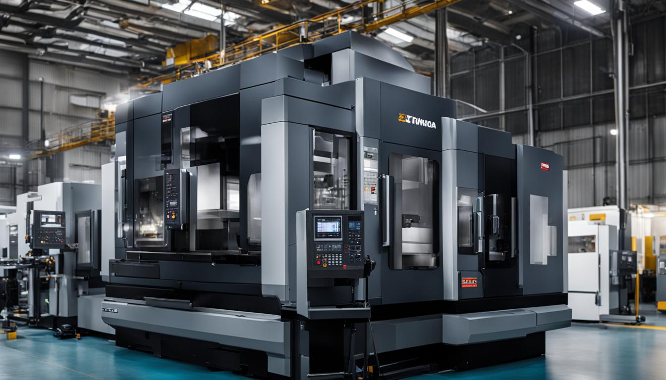
CNC turning centers represent a significant evolution from traditional CNC lathes, offering enhanced capabilities for complex part manufacturing. While both machine types rotate a workpiece against a cutting tool to remove material, their operational scope, axis configurations, and integrated features diverge considerably. Understanding these technical differences is crucial for optimizing production strategies and achieving specific part geometries.
A fundamental distinction lies in their axis capabilities. CNC lathes typically operate on two axes, X and Z, primarily performing cylindrical turning operations. In contrast, CNC turning centers can feature three, four, or even five axes, including Y and C axes, which enable more intricate machining tasks like milling, drilling, and tapping in a single setup.
Fundamental Design and Operational Philosophy
CNC lathes are foundational machine tools, primarily designed for creating parts with rotational symmetry. They excel at operations such as facing, threading, boring, and reaming on cylindrical workpieces. These machines are often simpler in design, focusing on efficient material removal through rotation.
Turning centers, however, are advanced, multi-functional machines that integrate capabilities beyond basic turning. They are often referred to as ‘turn-mill’ machines due to their ability to perform both turning and milling operations. This versatility allows for the complete machining of complex parts without requiring transfer to a separate milling machine, significantly reducing setup times and improving accuracy.
Machine Enclosures and Chip Management Systems
| Feature | CNC Lathe (Traditional) | CNC Turning Center (Advanced) |
|---|---|---|
| Axis Configuration | Typically 2 axes (X, Z) | 3 to 5+ axes (X, Y, Z, C, B) |
| Tooling System | Basic tool post or simpler turret, manual tool changes possible | Integrated multi-station turret (8-12+ tools), automatic tool changers |
| Live Tooling | Generally not available | Commonly integrated for milling, drilling, tapping |
| Sub-Spindle | Rarely present | Often integrated for backworking and simultaneous operations |
| Machine Enclosure | Can be open-frame or partially enclosed | Full machine enclosure for safety and chip containment |
| Chip Management | Manual or basic chip pan | Automated chip conveyor systems |
| Part Complexity | Primarily cylindrical, rotationally symmetrical parts | Complex geometries, parts requiring turning and milling |
| Production Scale | Small to medium batches, simpler parts | High-volume, complex part production |
| Standard Tolerance | ±0.005″ (±0.127 mm) | ±0.001″ to ±0.002″ (±0.025 to ±0.05 mm) for critical features |
Full machine enclosures are a hallmark of modern CNC turning centers, providing critical safety and operational benefits. These enclosures protect operators from flying chips, coolant splashes, and potential tool breakage, enhancing workplace safety.
Beyond safety, enclosures contribute to a cleaner workspace by containing dust, debris, and fluid spills, simplifying cleanup and maintaining environmental control around the machine. They also help reduce noise pollution, creating a more comfortable working environment.
Open-frame CNC lathes, while still utilized, present inherent safety challenges due to exposed rotating parts and flying debris. Operators must adhere to strict personal protective equipment (PPE) protocols, including eye protection and avoiding loose clothing or jewelry. Chip management in open-frame designs typically relies on manual removal, which is less efficient and poses greater risk.
Automated chip conveyors are integral to the high-production environment of CNC turning centers. These systems efficiently remove cutting waste from the machine, directly impacting uptime, surface quality, and coolant life. Various types, such as hinge-belt, scraper, and magnetic conveyors, are selected based on chip geometry, material, and coolant type.
Advanced Tooling and Spindle Configurations
Integrated tool turrets are a defining feature of CNC turning centers, significantly enhancing automation and efficiency. These turrets, often disk-shaped, hold multiple cutting tools—typically 8 to 12 positions—and can automatically index to present the correct tool for each operation. This automatic tool changing capability minimizes downtime and enables continuous machining.
Many turning centers incorporate ‘live tooling’ within their turrets, allowing for rotating tools to perform milling, drilling, and tapping operations. This capability transforms the machine into a multi-tasking platform, eliminating the need to transfer parts to a separate milling machine for secondary operations. The integration of a Y-axis further expands live tooling’s versatility, enabling off-center drilling and milling with simpler programming.
Sub-spindle integration is another advanced feature found in many CNC turning centers, particularly those designed for high-volume production. A sub-spindle, positioned opposite the main spindle, allows for simultaneous machining on both ends of a workpiece. This enables ‘backworking’ operations, where the part is transferred from the main spindle to the sub-spindle to complete the back side without manual intervention, dramatically reducing cycle times and improving part accuracy.
Optimizing for Production Throughput and Precision
Production speed scale is significantly higher on CNC turning centers due to their multi-axis capabilities, integrated live tooling, and sub-spindles. These features allow for complex parts to be completed in a single setup, minimizing part handling and reducing overall cycle times. Automated bar feeders further enhance continuous operation, making turning centers ideal for large-scale manufacturing.
Achievable tolerances in CNC turning operations are critical for part functionality. Standard tolerances for CNC machining typically range from ±0.005 inches (±0.127 mm) for most metals, achievable with common tooling. For applications requiring higher precision, turning operations can reliably hold ±0.001 to ±0.002 inches (±0.025 to ±0.05 mm) under optimized conditions.
Feeds and speeds are meticulously calculated parameters that directly influence surface finish, tool life, and material removal rates. For aluminum, recommended spindle speeds can range from 8,000 to 12,000 RPM with feed rates of 40-80 IPM. Mild steel typically requires lower RPMs, around 6,000-9,000, with feed rates of 20-40 IPM. These parameters are adjusted based on material density, tool geometry, and machine rigidity.