
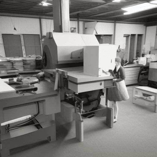
Milling is a subtractive manufacturing process that precisely removes material from a workpiece using rotating multi-point cutting tools. This versatile machining method is fundamental to producing components across nearly all industrial sectors, from aerospace to medical devices. It relies on controlled machine movement and tool engagement to achieve desired geometries and surface finishes.
The core principle involves a cutting tool rotating at high speed while simultaneously moving relative to a stationary or moving workpiece. This interaction generates chips, progressively shaping the raw material into the final part. Understanding the intricate dynamics of this process is essential for optimizing efficiency and part quality.
Subtractive Material Removal
Subtractive material removal defines milling as a process where material is removed from a solid block, billet, or casting to create a desired shape. Unlike additive manufacturing, which builds up material, milling carves it away. This method is highly effective for achieving tight tolerances and complex features.
The cutting action occurs as the rotating tool’s flutes engage the workpiece, shearing off small pieces of material. This shearing process is influenced by the material’s properties, the tool’s geometry, and the programmed cutting parameters. Different milling operations, such as face milling for large flat surfaces or peripheral milling for contours, dictate how the tool engages the material.
Modern milling strategies, like High-Efficiency Milling (HEM), optimize material removal rates by employing a light radial depth of cut (RDOC) and a deeper axial depth of cut (ADOC). This approach distributes wear more evenly across the cutting edge, dissipates heat effectively, and allows for higher feed rates, significantly reducing roughing cycle times.
Workpiece Mounting
| Material | Condition | Cutting Speed (SFM) | Feed per Tooth (in/tooth) | Notes |
|---|---|---|---|---|
| Aluminum 6061 | T6 | 800 – 1500+ | 0.003 – 0.008 (for 1/4″-1/2″ tool) | High helix angles, polished flutes, coolant recommended. |
| 4140 Steel | Annealed (~197 HB) | 250 – 400 | 0.002 – 0.008 (depending on tool/DOC) | Coated carbide, PVD AlTiN for milling. |
| 4140 Steel | Pre-hardened (28-32 HRC) | 120 – 200 | Higher feed rates for high-feed geometry. | Reduce speeds for full-width cuts. |
Securely mounting the workpiece is paramount in milling to prevent movement, vibration, and potential damage to the part or machine. Workholding devices must provide sufficient clamping force and rigidity to withstand cutting forces. Improper workholding can lead to dimensional inaccuracies, poor surface finish, and tool breakage.
Common workholding solutions include vices, which clamp the workpiece between two jaws, and various clamping systems like step clamps or toe clamps that utilize T-slots on the machine bed. Custom fixtures are often designed for complex or high-volume parts, ensuring repeatable positioning and optimal access for the cutting tool. Magnetic chucks offer quick setup for ferrous materials, particularly useful for thin or delicate parts where traditional clamping might cause distortion.
Establishing accurate datum features on the workpiece is critical for precise machining. These reference points ensure that the part is correctly aligned with the machine’s coordinate system. Machined surfaces are preferred for clamping due to their inherent parallelism, which maximizes contact area and clamping stability.
Rotary Tool Engagement
Rotary tool engagement involves the interaction between the spinning cutting tool and the workpiece material. The selection of the appropriate milling cutter is a critical engineering decision, directly impacting surface finish, tool life, and dimensional accuracy.
End mills are among the most common milling cutters, available in various geometries such as square-end, ball-nose, and corner-radius, each suited for specific profiling, slotting, or contouring tasks. Face mills, often equipped with indexable inserts, are designed for efficient material removal over large flat surfaces. Solid carbide and diamond-coated cutters are frequently used in modern CNC milling operations for their performance and longevity.
Feeds and speeds, which define the spindle speed (RPM) and the rate at which the tool advances into the material (IPM), are calculated based on the material, tool diameter, number of flutes, and desired chip load. For instance, milling 6061 aluminum with a carbide end mill typically involves high cutting speeds, ranging from 1000 to 4000 surface feet per minute (SFM), to prevent material from sticking to the tool and ensure efficient chip evacuation.
Multi-Axis Travel
Multi-axis milling extends the capabilities of traditional 3-axis machines by incorporating additional rotary axes, typically a fourth and fifth axis. This allows the cutting tool to approach the workpiece from multiple angles, enabling the creation of highly complex geometries and undercuts that would be impossible with fewer axes.
The primary advantage of multi-axis machining lies in its ability to complete complex parts in a single setup, significantly reducing the need for multiple re-fixturing operations. This not only increases part accuracy by maintaining consistent datums but also optimizes production efficiency and lowers labor costs. Multi-axis machines also facilitate the use of shorter cutting tools, which reduces vibrations and leads to superior surface finishes.
Multi-axis milling is particularly beneficial for parts with angled holes, compound-angle faces, deep cavities, or turbine-like surfaces. Both indexed positioning, where the workpiece is rotated to a fixed angle, and simultaneous 5-axis motion, where all axes move concurrently, are employed depending on the part’s complexity and desired surface continuity.
Chip Formation and Clearance
Chip formation is a fundamental aspect of metal cutting, where material undergoes plastic deformation and shearing ahead of the cutting edge, separating from the workpiece as a chip. The type of chip formed—continuous, discontinuous, or segmented—is influenced by workpiece material properties, tool geometry, and cutting conditions.
Continuous chips, often seen with ductile materials like aluminum or steel at high cutting speeds, can be problematic if not managed, potentially damaging the machine, workpiece, or tool, and posing safety risks. Effective chip control is crucial to break these long chips into manageable segments, often achieved through specific tool geometries or chip breakers.
Efficient chip clearance, or evacuation, is equally vital to prevent re-cutting of chips, which can degrade surface finish, increase heat, and cause tool wear. Coolants, lubricants, or air blasts are commonly used to flush chips away from the cutting zone. Proper chip evacuation ensures consistent cutting action, extends tool life, and maintains part quality.
Standard Tolerances and Surface Finish
Achieving specific dimensional tolerances and surface finishes is a key objective in precision milling. ISO 2768 is a widely adopted standard that defines general tolerances for linear and angular dimensions when specific tolerances are not explicitly indicated on engineering drawings. This standard includes four tolerance classes: ‘f’ (fine), ‘m’ (medium), ‘c’ (coarse), and ‘v’ (very coarse), with ‘m’ being the most common general-purpose default.
Surface finish, quantified by parameters like Ra (Average Roughness), describes the texture of the machined surface. A standard as-machined surface roughness for CNC milling is typically Ra 3.2 µm (125 µin), suitable for many structural and functional components. Finer finishes, down to Ra 0.2 µm, can be achieved for precision parts requiring smoother surfaces for sealing, bearing, or aesthetic purposes, though these often incur higher costs due to tighter tool control and slower feed rates.