
Operating Computer Numerical Control (CNC) machines efficiently requires a deep understanding of potential issues that can arise during production. These machines, while highly precise, are susceptible to various problems that can compromise part quality, increase downtime, and escalate operational costs. Proactive identification and resolution of these challenges are critical for maintaining optimal machining performance and extending equipment lifespan.
From unexpected tool failures to subtle vibrations, each issue demands a systematic approach to diagnosis and correction. Modern manufacturing relies heavily on the reliability of CNC systems, making it imperative for engineers and machinists to be well-versed in troubleshooting common operational difficulties.
Tool Breakage and Wear
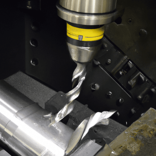
Tool breakage and premature wear represent significant concerns in CNC machining, directly impacting productivity and part quality. Excessive mechanical load is a primary culprit, often stemming from an overly high feed per tooth, excessive axial or radial depth of cut, or unexpected entry into heavy corners. Workpiece hardness exceeding expectations or using a tool geometry unsuitable for the operation also contributes to this issue.
Incorrect cutting parameters, such as inappropriate spindle speed or feed rate, can also lead to rapid tool degradation. When the spindle speed is too high or too low, the cutting edges may rub instead of cutting cleanly, generating uneven forces and heat. Poor chip evacuation, where chips pack in the flutes, can also cause mechanical overload and subsequent tool failure.
Tool deflection, excessive tool stick-out, and poor workholding further exacerbate tool breakage risks. A longer tool acts less rigidly, making it more prone to bending and vibrating during cutting. Maintaining clean collets and ensuring proper torque during tool clamping are essential to prevent slippage and reduce runout, which can otherwise lead to uneven cutting forces and premature wear.
Modern tooling practices emphasize selecting the correct tool material and coating for the specific application. Carbide tools, for instance, offer greater stiffness than high-speed steel (HSS) and can reduce chatter, while advanced coatings provide enhanced wear resistance and improved chip flow. Regular inspection for signs of wear, such as small chips, cracks, or uneven flute wear, allows for timely tool replacement before catastrophic failure occurs.
Overheating Spindle Bearings
| Parameter | Description | Typical Range/Value |
|---|---|---|
| Cutting Force (F_cut) | Force exerted by the tool on the workpiece. | Calculated from specific cutting force, depth of cut, radial engagement. |
| Safety Factor (n) | Multiplier for F_cut to ensure adequate holding. | 2-3 (continuous milling), 3-5 (interrupted milling). |
| Friction Coefficient (μ) | Between jaws and workpiece. | 0.15-0.25 (smooth jaws), 0.4-0.6 (serrated jaws on steel). |
| Clamping Force (F_clamp) | Minimum force required to prevent slippage. | F_clamp ≥ (F_cut × n) / μ. |
Spindle overheating is a critical issue that can lead to significant damage, affecting machining accuracy and overall machine lifespan. Common causes include overloading the spindle, poor lubrication, inefficient cooling systems, and worn bearings. Operating the spindle beyond its rated torque or speed capacity generates excessive heat, stressing the motor and bearings.
Inadequate or contaminated lubrication increases friction within the bearings, accelerating wear and heat buildup. Modern spindle bearings often require specific high-quality lubricants, and adherence to manufacturer-recommended lubrication schedules is crucial. Over-lubrication can be as detrimental as under-lubrication, disrupting the delicate balance required for optimal performance.
Cooling system inefficiencies, such as clogged filters, low coolant levels, or malfunctioning pumps, impair the spindle’s ability to dissipate heat effectively. For air-cooled spindles, restricted airflow due to dust or debris can trap heat, while water-cooled systems require proper fluid levels and clear pipelines. High ambient temperatures or poor ventilation in the workshop can also reduce the spindle’s cooling capacity.
Worn or damaged bearings naturally generate more friction and heat over time, leading to increased resistance and potential spindle failure. Misalignment during installation or an overtight bearing preload can also contribute to localized overheating. Monitoring tools, such as thermal imaging and vibration analyzers, can help diagnose these issues early, preventing costly repairs and downtime.
G-Code Programming Errors
G-code programming errors are a frequent source of CNC machine malfunctions, leading to incorrect toolpaths, damaged parts, and potential collisions. Even minor syntax issues, such as missing characters or improper spacing, can cause a line to be ignored or trigger alarms. For instance, using ‘MO’ instead of ‘M0’ (program stop) can result in unexpected machine behavior.
Confusion between absolute (G90) and incremental (G91) coordinate systems is a common mistake, causing unintended movements. Forgetting to specify the correct plane selection (G17, G18, G19) can also lead to errors, especially in complex multi-axis operations. These ‘modal’ commands remain active until explicitly changed, making it easy for programmers to overlook their current state.
Critical errors include programming a rapid traverse (G00) into the workpiece instead of a controlled linear interpolation (G01), which can cause severe tool breakage or machine crashes. Omitting feed rate (F) or spindle speed (S) commands for cutting motions (G01, G02, G03) can result in alarms or unsafe cutting speeds. Similarly, forgetting to activate tool length compensation (G43) or leaving a canned cycle active (G80) can lead to dimensional inaccuracies or unexpected tool behavior.
Modern engineering practices emphasize rigorous G-code verification through simulation software before execution on the machine. Post-processor issues, where the CAM software generates incorrect G-code for a specific machine controller, also require careful review. Adopting disciplined code validation and simulation practices significantly reduces the risk of errors, improving machining outcomes.
Workpiece Slippage
Workpiece slippage during CNC machining is a critical problem that compromises dimensional accuracy, surface finish, and tool life, while also posing safety risks. This occurs when the clamping mechanism fails to generate sufficient friction or holding force to counteract the cutting loads. Insufficient clamping force is the most common mistake, often due to under-tightening or uneven force distribution.
Using the wrong type of clamp for the workpiece geometry, such as a vise for an irregular shape or a strap clamp for a round part, can also lead to instability. Poor fixture stability, where the clamp itself is not securely mounted or the machine table is not clean, creates pivot points for vibration and movement. Even a small chip under the workpiece can compromise clamping integrity.
Material properties play a role; smooth, polished, or oily surfaces inherently have a lower coefficient of friction, making them more prone to slipping. Proper workpiece preparation, including cleaning and potentially knurling gripping surfaces, can enhance friction. Thin or flexible materials are particularly susceptible to bending or movement if clamping pressure is uneven.
Excessive machining forces, resulting from overly aggressive cuts, high feed rates, or dull tools, can overwhelm the clamping system. Calculating the required clamping force is essential, typically involving the cutting force, a safety factor (2-3 for continuous milling, 3-5 for interrupted), and the friction coefficient of the jaws. Modern workholding solutions, such as self-centering vises, hydraulic clamping, and zero-point systems, offer enhanced rigidity and repeatability.
Chattering and Vibration
Chattering and vibration are detrimental phenomena in CNC machining, leading to poor surface finish, reduced dimensional accuracy, accelerated tool wear, and decreased machine life. Chatter is a self-excited vibration that arises from dynamic instabilities between the cutting tool and the workpiece, amplifying existing vibrations in the system. This often manifests as a high-pitched squeal and visible marks on the part.
Common causes include insufficient machine or setup rigidity, excessive tool overhang, and poor workholding that allows workpiece movement. A long, thin tool acts like a tuning fork, amplifying vibrations, hence the recommendation to use the shortest possible tool length. Unstable cutting parameters, particularly an incorrect combination of spindle speed and depth of cut, can also induce chatter.
Optimizing cutting parameters is crucial for chatter suppression. Adjusting spindle speed by 10-20% can shift the cutting frequency away from the machine’s natural resonant frequencies, moving into a ‘stable lobe’ region. Increasing the feed rate can sometimes be counterintuitive but effective, as it increases chip thickness and reduces rubbing, favorably altering the cutting dynamics. Maintaining the correct chip load is also vital; too light a chip load causes rubbing, while too heavy a load leads to excessive force and deflection.
Modern solutions include variable helix angle tools and variable pitch end mills, which disrupt harmonic frequencies that cause chatter. High-quality, balanced tool holders, such as hydrostatic or shrink-fit types, can dampen vibrations more effectively. Advanced CNC machines may incorporate features like Okuma’s Machining Navi system or Haas’s Spindle Speed Variation (SSV), which automatically adjust spindle speed to mitigate chatter. Vibration analysis, using sensors to monitor acceleration and velocity signatures, provides real-time insights into bearing health and overall machine stability, enabling predictive maintenance.