
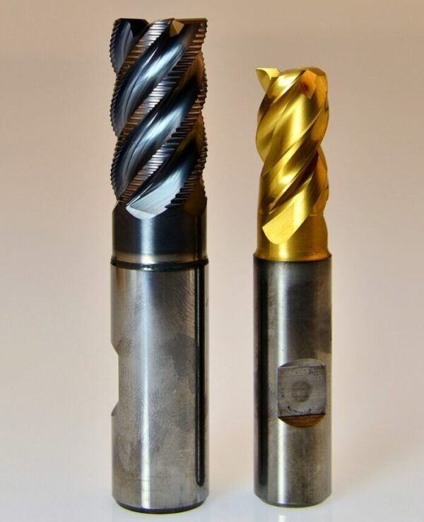
Effective CNC milling relies heavily on selecting the correct cutting tools. Understanding the intricate relationship between tool geometry, material composition, protective coatings, flute count, and precise speeds and feeds is paramount for achieving optimal part quality, maximizing tool life, and ensuring efficient material removal. Modern machining demands a data-driven approach to tooling decisions.
Standard CNC machining tolerances typically range from ±0.05 mm to ±0.13 mm for most milling and turning operations, representing the baseline capability of contemporary CNC equipment. Achieving tighter tolerances, such as ±0.01 mm, is possible with standard CNC milling equipment but necessitates careful process control, appropriate tooling, and experienced operators. Material properties significantly influence achievable tolerances; for instance, aluminum alloys can achieve ±0.05 mm, while stainless steel typically allows ±0.10 mm.
End Mill Geometries and Their Applications
End mill geometries are engineered for specific cutting tasks and material characteristics. Square end mills, with their sharp 90-degree corners, are ideal for creating sharp corners, slotting, and general-purpose milling. Ball nose end mills, featuring a spherical cutting tip, are essential for 3D contouring, mold making, and producing smooth, radiused surfaces.
Corner radius end mills, also known as bull nose end mills, incorporate a small radius at the corner, offering a compromise between the strength of a square end mill and the reduced stress concentration of a ball nose. This design enhances tool life by distributing cutting forces over a larger area, making them suitable for roughing and semi-finishing operations where edge chipping is a concern.
Roughing end mills, often called ‘corn cob’ cutters, feature serrated cutting edges designed to break chips into smaller, more manageable pieces. This geometry facilitates high material removal rates and reduces cutting forces, making them excellent for aggressive roughing passes, particularly in tough materials. Finishing end mills, conversely, prioritize surface finish and dimensional accuracy, typically having a smoother cutting edge and often a higher flute count.
Cutting Tool Materials: Carbide versus HSS
| Feature | High-Speed Steel (HSS) | Solid Carbide |
|---|---|---|
| Hardness (HRC) | 62-65 (M2), 65-67 (M42) | ~70-80 (equivalent HRC) |
| Stiffness (Young’s Modulus) | ~200-210 GPa | ~600 GPa |
| Toughness | High (flexes, less prone to shatter) | Lower (brittle, prone to chipping) |
| Max Cutting Speed | Lower (e.g., 500 RPM for mild steel) | Higher (2-12x HSS, e.g., 2670 RPM for mild steel) |
| Cost | Lower initial cost | Higher initial cost |
| Best Use Cases | Soft materials, prototypes, short runs, less rigid machines | Hard materials, high-volume production, high-speed machining, precision |
Choosing between solid carbide and High-Speed Steel (HSS) for end mills involves a critical trade-off between performance, toughness, and cost. HSS, an alloyed tool steel, offers excellent toughness and forgiveness, making it less prone to shattering under vibration or interrupted cuts. It remains a cost-effective choice for softer materials, prototyping, short runs, or less rigid machine setups.
Solid carbide, a composite of tungsten carbide grains sintered with a cobalt binder, is significantly harder and stiffer than HSS, with a Young’s modulus roughly three times greater. This rigidity translates to tighter dimensional tolerances and straighter walls due to minimal tool deflection. Carbide tools excel in high-speed machining, allowing for significantly faster cutting speeds and feeds, which reduces cycle times and improves chip evacuation.
While carbide end mills typically cost three to five times more than HSS equivalents, their extended tool life and higher productivity often result in a lower cost-per-part, especially in high-volume production or when machining harder materials like stainless steel, titanium, and heat-resistant superalloys. HSS, however, is more easily resharpened and can be a smarter choice for jobs where flexibility and lower initial investment are prioritized.
Advanced Coatings for Enhanced Performance
Tool coatings are thin, hard layers applied to the tool’s surface, typically via Physical Vapor Deposition (PVD) or Chemical Vapor Deposition (CVD) processes. These coatings significantly improve tool performance by increasing surface hardness, reducing friction, and providing thermal protection, leading to extended tool life and improved cutting efficiency.
Titanium Nitride (TiN) is a foundational coating, recognizable by its golden color. It provides increased surface hardness (around 2,000-2,500 HV) and wear resistance, with thermal stability up to approximately 500-600°C. TiN is a general-purpose coating effective for ferrous materials, often tripling tool life compared to uncoated tools in carbon and low-alloy steels.
Aluminum Titanium Nitride (AlTiN) is a more advanced PVD coating, dark gray or black in color, offering superior performance for demanding applications. Its higher aluminum content (often >50%) enables the formation of a protective aluminum oxide layer at elevated cutting temperatures, providing exceptional oxidation and heat resistance up to 800-900°C. AlTiN is particularly effective for dry, high-heat cutting of titanium, stainless steel, Inconel, and cast iron, significantly boosting hardness (4,000-4,200 Hv) and wear resistance. However, AlTiN should be avoided when machining aluminum, as the chemical affinity between the coating’s aluminum and the workpiece can cause material to weld to the tool.
Optimizing Flute Count for Diverse Materials
The number of flutes on an end mill is a critical design choice directly impacting chip evacuation, tool rigidity, and surface finish. Generally, fewer flutes (2-3) are preferred for softer, non-ferrous materials like aluminum and plastics, while more flutes (4 or more) are better suited for harder, ferrous materials such as steel, titanium, and superalloys.
Two-flute end mills feature larger ‘gullets’ or valleys between the cutting edges, which are essential for evacuating the large, curling chips produced when machining soft materials like aluminum. This design prevents chip packing and allows for higher material removal rates. Three-flute end mills offer a performance-enhancing alternative for non-ferrous metals, providing a faster feed rate for a given surface speed and improved roughing capabilities.
For harder materials like steel and cast iron, 4-flute end mills are standard. More flutes mean a larger core diameter, which significantly increases tool rigidity and reduces deflection and chatter, leading to better surface finishes. End mills with five or more flutes are ideal for very tough materials such as titanium, high-temperature nickel alloys, and stainless steels. These high-flute tools distribute cutting forces across more edges, reducing wear per cutting edge and maintaining higher feed rates even at lower spindle RPMs, especially in High-Efficiency Milling (HEM) strategies.
Calculating Feeds and Speeds for Machining Efficiency
Accurate calculation of feeds and speeds is fundamental to efficient CNC machining, directly influencing tool life, surface finish, and material removal rates. The two primary parameters are spindle speed (RPM) and feed rate (IPM or mm/min), both derived from the material’s optimal Surface Feet per Minute (SFM) and the desired chip load per tooth.
Surface Feet per Minute (SFM) represents the linear speed at which the cutting edge moves across the workpiece. It is a material-dependent constant, meaning different materials have optimal SFM ranges. The spindle speed (RPM) is then calculated using the tool’s diameter and the chosen SFM. The formula for RPM in inches is: RPM = (SFM × 3.82) ÷ Tool Diameter (in inches). For metric calculations, RPM = (1000 × Cutting Speed in m/min) / (π × Tool Diameter in mm).
The feed rate, or Inches Per Minute (IPM), determines how quickly the tool advances through the material. It is calculated based on the RPM, the number of flutes (Z), and the chip load per tooth (FPT or IPT), which is the amount of material each cutting edge removes. The formula for IPM is: IPM = RPM × FPT × Z. Chip load is a critical factor, as incorrect values can lead to premature tool wear, poor surface finish, or tool breakage. Modern practice often involves starting with conservative values (e.g., 80% of calculated) and adjusting based on the sound of the cut and chip formation.
Depth of cut also plays a significant role in determining appropriate feeds and speeds. Axial depth of cut (Ap) refers to how deeply the tool engages along its axis, while radial depth of cut (Ae), or stepover, is the engagement across the tool’s width. For roughing operations in steel, axial depth can be equal to the tool diameter with 30-50% radial engagement. In aluminum, axial roughing depths of 3-6 mm are common, with radial depth often limited to 50% of the cutter diameter for roughing. Finishing passes typically use much lighter depths of cut to achieve desired surface finishes and maintain tight tolerances.