
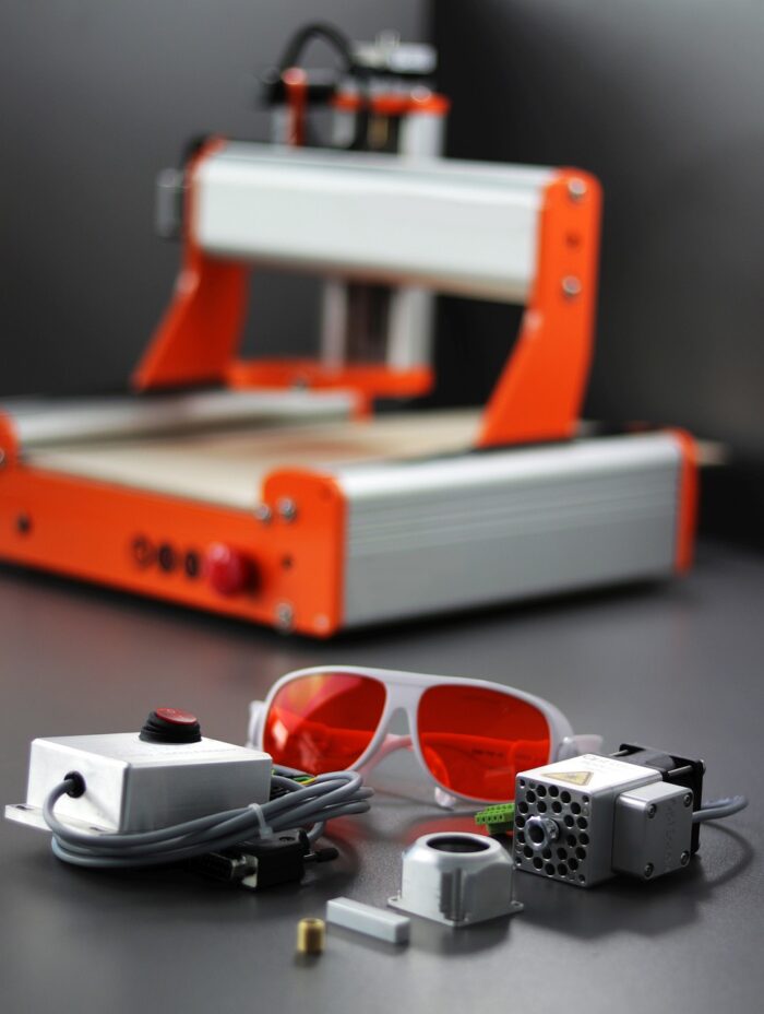
Constructing a Computer Numerical Control (CNC) machine from scratch or assembling a kit offers a profound understanding of subtractive manufacturing principles. This endeavor requires careful consideration of mechanical, electrical, and software components to achieve precise and repeatable motion. Engineers and hobbyists alike benefit from a structured approach to design, component selection, and calibration.
This guide delves into the technical aspects of DIY CNC, covering critical decisions from frame construction to software configuration. Adhering to established engineering practices ensures a robust and accurate machine capable of diverse machining tasks. Precision in every step minimizes errors and maximizes operational efficiency.
Building Your CNC: Kit versus Scratch
The initial decision for any aspiring CNC builder involves choosing between a pre-designed kit and a completely custom, scratch-built machine. CNC kits provide a streamlined assembly process, often including all necessary mechanical components, electronics, and detailed instructions. This approach significantly reduces the complexity of sourcing individual parts and ensures compatibility across the system.
Opting for a scratch build, conversely, allows for unparalleled customization and a deeper learning experience. Builders can select specific components tailored to unique performance requirements, such as larger work envelopes or specialized spindle types. This path demands a comprehensive understanding of mechanical design, material science, and electrical integration.
While kits offer convenience, a scratch build provides maximum flexibility in material choice and structural design. For instance, a custom machine might incorporate heavier-duty linear rails or a more robust gantry system than typically found in entry-level kits. The trade-off often involves increased design time and potential troubleshooting challenges.
Cost considerations also influence this choice. Kits often present a predictable upfront expense, though upgrades can add to the total. Scratch builds can sometimes be more economical if components are sourced strategically, but unexpected issues may lead to unforeseen expenditures.
Stepper Motor Selection and Sizing
| NEMA Size | Faceplate Size (mm) | Typical Holding Torque (N·cm) | Rated Current (A) | Shaft Diameter (mm) |
|---|---|---|---|---|
| NEMA 17 | 42 x 42 | 30–80 | 0.8–2.0 | 5 |
| NEMA 23 | 57 x 57 | 120–300 | 2.0–4.5 | 6.35–8 |
| NEMA 34 | 86 x 86 | 400–1200 | 4.0–8.0 | 12–14 |
Selecting appropriate stepper motors is fundamental to a CNC machine’s performance, directly impacting torque, speed, and positional accuracy. Stepper motors provide precise, repeatable positioning at a fraction of the cost of servo motors, making them the preferred choice for most DIY and light commercial CNC applications. Proper sizing prevents missed steps, overheating, and stalled motion during operation.
NEMA standards define the motor’s mounting face dimensions, with numbers like 17, 23, and 34 indicating the flange size in tenths of an inch. Larger NEMA sizes generally correlate with increased physical volume, weight, and torque output. For desktop routers under 600 mm travel, NEMA 23 motors with 1.0–1.8 N·m holding torque are typical. Mid-size machines (600–1200 mm travel) often utilize NEMA 23 at 1.8–2.5 N·m or NEMA 34 at 3–5 N·m.
Motor sizing involves calculating peak cutting force, inertia, and friction, then converting these to required motor torque. Ball screws typically achieve 90% efficiency, while acme/leadscrews rarely exceed 20% efficiency, significantly affecting torque requirements. A safety factor of 1.5 to 2.0 is recommended to account for unmodeled friction, voltage sag, and temperature effects.
The driver voltage should be selected based on the motor’s winding inductance; higher voltage pushes current faster, extending usable torque to higher RPMs. For wood and plastic routing, a pair of NEMA 23 motors (e.g., 1.8 N·m) is usually sufficient, while aluminum milling or heavy gantries often require NEMA 34 motors (4+ N·m).
Controller Software: GRBL and Mach3 Setup
The choice of CNC controller software dictates how G-code is interpreted and translated into machine motion. GRBL and Mach3 represent two popular, yet distinct, solutions for DIY and hobbyist CNC machines. GRBL is an open-source firmware designed for Arduino-based CNC systems, offering a low-cost, high-performance controller.
Installing GRBL typically involves uploading the firmware to an Arduino UNO board using the Arduino IDE. This process requires downloading the GRBL source code, adding it as a library, and then compiling and uploading the ‘GrblUpload’ example sketch. An Arduino CNC Shield simplifies connecting stepper motor drivers (like A4988 or DRV8825) and other peripherals.
Mach3, a Windows-based CNC motion controller, drives stepper and servo amplifiers through a parallel port or an external motion controller. Its installation involves running an executable, accepting license terms, and often copying specific configuration files like ‘Mach3Mill.xml’ to the installation directory. Mach3 requires a compatible operating system, historically Windows XP and Windows 7 for parallel port control, though external motion devices expand compatibility.
After installation, Mach3 requires configuration of motor tuning, input/output signals, and other parameters to match the specific machine hardware. Both GRBL and Mach3 translate G-code into step and direction signals for motor drivers, enabling precise axis movement.
Constructing with Aluminum Extrusion Frames
Aluminum extrusion frames, particularly those utilizing the ’80/20′ T-slot system, are a cornerstone of modern DIY CNC machine construction. These modular profiles offer significant advantages in ease of assembly, flexibility, and adaptability. The T-slot design allows for components, brackets, and panels to be mounted and repositioned without welding, simplifying prototyping and modifications.
While aluminum is lighter than steel, it possesses lower inherent stiffness. Therefore, careful selection of profile size is crucial for maintaining rigidity, especially for machines subjected to cutting forces or heavy moving parts. Profiles like 2020, 2040, 4040, and 4545 are common, with larger profiles offering increased bending resistance for longer spans or higher loads.
Frame design must consider both static and dynamic loads. Static loads involve constant weight, while dynamic loads introduce movement, vibration, or impact forces. For applications with dynamic loading, upsizing the profile by at least one series beyond static calculations is recommended to prevent fatigue and unexpected failures. The moment of inertia (I) is a key specification, as higher values indicate stiffer profiles that deflect less under load.
Assembly techniques typically involve specialized fasteners, T-nuts, and corner brackets that slide into the extrusion’s slots. This modularity not only simplifies initial construction but also facilitates future upgrades or repairs. The smooth, flat surfaces of anodized aluminum extrusions also contribute to a clean, professional aesthetic.
Essential Initial Calibration Steps
Achieving accurate and repeatable cuts on a CNC machine hinges on meticulous initial calibration. This process ensures that programmed movements precisely translate into physical motion, mitigating errors and improving part quality. A stable environment and fundamental mechanical checks, such as leveling the machine frame, precede any software adjustments.
Calibrating ‘steps per millimeter’ (SPMM) for each axis is a critical software parameter. This setting tells the controller how many motor steps are required to move the axis a specific linear distance. To calibrate, a precision ruler or dial indicator is used to measure the actual travel distance after commanding a known movement. The formula ‘Updated Steps/mm = (Current Steps/mm) x (Commanded Travel) / Dial Indicator Reading’ is then applied to refine the setting. This iterative process is performed for the X, Y, and Z axes.
Backlash compensation addresses mechanical play in leadscrew or ball nut drives, which can cause inaccuracies when an axis changes direction. While mechanical reduction of backlash is always preferred, software compensation can be implemented in controllers like Mach3. In Mach3, backlash values are measured with a dial indicator and entered into the ‘Config > Backlash’ dialog, with a ‘Backlash Speed’ setting to control the compensation move. It is crucial to restart Mach3 after enabling or disabling this feature.
Squaring the gantry and ensuring the spindle is perpendicular to the machine bed (tramming) are also vital mechanical calibration steps. A tramming tool or dial indicator mounted in the spindle can sweep the bed surface to identify and correct any tilt. These mechanical alignments establish a true reference plane for all subsequent machining operations, contributing significantly to overall precision.