
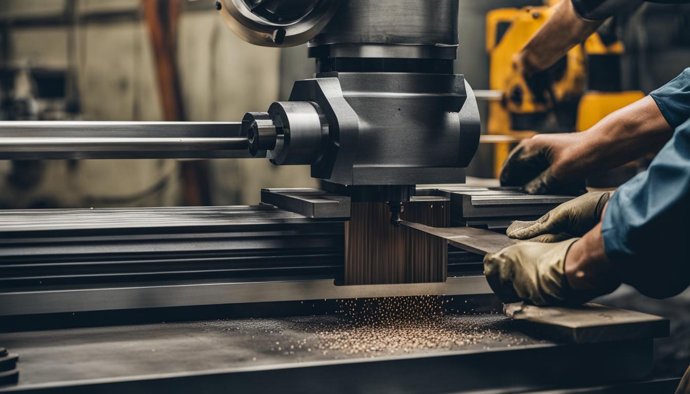
Manual milling machines remain indispensable tools in modern workshops, offering unparalleled versatility for prototyping, small-batch production, and repair work. These machines empower skilled operators to directly control cutting actions, relying on precision hand-eye coordination rather than complex programming. Understanding fundamental operations is key to unlocking their full potential and achieving high-quality results.
While CNC machines dominate high-volume manufacturing, manual mills excel in scenarios demanding flexibility and direct operator intervention. They are particularly valuable for intricate mold making, scribing, chiseling, and machining forming surfaces. The foundational skills learned on a manual mill translate directly to a deeper understanding of all subtractive manufacturing processes.
Introduction to Manual Milling Fundamentals
Operating a manual milling machine involves precise control over the workpiece and cutting tool across multiple axes. Operators manipulate handwheels to govern movement along the X (longitudinal), Y (traverse), and Z (vertical) axes, dictating the cutting path and depth. This direct interaction allows for immediate adjustments based on visual feedback and the machine’s sound.
Modern manual mills often integrate Digital Readouts (DROs), power feeds, and variable spindle speeds, significantly enhancing accuracy and ease of use. A DRO system displays real-time positional data, typically to 0.0002 inches (5 microns) or better, reducing reliance on counting handwheel turns and minimizing human error. This technology transforms a manual machine into a more precise and efficient instrument.
Executing Basic Face Milling Passes
| Operation / Material | Cutter Type | Surface Speed (SFM) | Chip Load (in/tooth or in/rev) | Axial Depth of Cut (DOC) |
|---|---|---|---|---|
| Face Milling – Aluminum | Carbide Insert Face Mill | 600-1000 | 0.003-0.005 | 0.010-0.050″ (Finish) |
| Face Milling – Mild Steel | Carbide Insert Face Mill | 300-500 | 0.002-0.004 | 0.005-0.030″ (Finish) |
| Drilling – Aluminum | HSS Twist Drill | 200-250 | 0.005-0.010 (per rev) | Up to 1x Diameter (Peck for deeper) |
| Drilling – Mild Steel | HSS Twist Drill | 80-110 | 0.002-0.006 (per rev) | Up to 1x Diameter (Peck for deeper) |
| Slotting – Aluminum | 2-3 Flute Carbide End Mill | 600-1000 | 0.002-0.004 | 0.125-0.250″ (Reduce for full slot) |
| Slotting – Mild Steel | 2-4 Flute Carbide End Mill | 300-500 | 0.001-0.003 | 0.060-0.125″ (Reduce for full slot) |
Face milling is a primary operation designed to create flat, smooth surfaces on a workpiece. This process involves a rotating cutter, typically larger in diameter than the material width, removing material from the top surface. Proper tool selection and machine setup are critical for achieving desired flatness and surface finish.
Common face milling cutters include indexable face mills, which use replaceable carbide inserts, and solid carbide face mills, prized for their rigidity and precision. A 45-degree entering angle face mill is often preferred for general surfacing due to its balanced cutting forces and smooth action. For roughing, increased depth of cut with reduced feed per tooth is common, while finishing passes require shallow depths and often higher feed rates for a superior surface.
For a 2-3 HP Bridgeport-class machine, face mills between 1.5 to 3 inches in diameter are generally recommended. Larger diameters can generate excessive radial forces, potentially damaging spindle bearings. Maintaining machine stability and proper alignment is paramount to prevent vibration and ensure a consistent, high-quality finish.
Achieving Precision in Hole Drilling
Drilling on a milling machine provides superior accuracy and rigidity compared to a drill press, allowing for precise hole placement and depth control. Standard twist drills are commonly used, but specialized drill bits exist for various materials and applications. Proper speeds and feeds are essential to prevent tool breakage and ensure clean holes.
When drilling, the spindle speed (RPM) is calculated based on the cutting speed (SFM) of the material and the drill diameter. Feed rate, expressed in inches per minute (IPM) or inches per revolution (IPR), depends on the spindle speed and the drill’s chip load per revolution. For manual operations, a general rule of thumb for feed is 0.001 inches per revolution for every 1/16 inch of drill diameter.
Deeper holes, especially those exceeding three drill diameters, often require peck drilling to clear chips and prevent heat buildup. This involves retracting the drill periodically to allow coolant to reach the cutting edge and evacuate chips. Adequate lubrication, whether flood coolant or manual oil application, is crucial for tool life and chip evacuation.
Cutting Accurate Straight Slots
Creating straight slots on a manual mill requires careful setup and appropriate tooling to maintain accuracy and prevent cutter deflection. End mills are the primary tools for slotting, with 2-flute or polished 3-flute carbide end mills often preferred for aluminum to facilitate chip evacuation. For steel, robust carbide end mills are typically used.
Slotting is inherently more challenging than side milling because the cutter is fully engaged on both sides, restricting chip escape and increasing cutter load. To mitigate this, feed rates should be reduced, often by 30-50% compared to side-milling values. Axial depth of cut should also be modest, especially for initial passes, to manage spindle load and ensure effective chip removal.
For roughing slots, a roughing end mill can remove material quickly, followed by a finishing end mill for precise dimensions and a smooth finish. Using compressed air or flood coolant is vital to clear chips from the slot, preventing recutting and extending tool life. Listening to the machine’s sound and observing chip formation provides valuable feedback for optimizing feed rates.
Applying Chamfers to Plate Edges
Chamfering is a common milling operation used to bevel edges, improving safety by removing sharp corners, enhancing aesthetics, and preparing parts for welding or deburring. Various chamfer mills are available, including solid carbide and indexable insert types, with angles ranging from 15 to 80 degrees.
Chamfer cutters come in different tip geometries, such as pointed and flat-tip designs. Pointed tips are advantageous for smaller grooves, slots, and holes, offering easier programming and touch-offs due to their precise tip location. Flat-tip designs provide greater strength and are suitable for general edge chamfering.
The choice of chamfer mill material, typically solid carbide for smaller diameters, is influenced by the workpiece material. Aluminum and non-ferrous materials benefit from sharp cutting edges and polished flutes to prevent material buildup. For harder materials, robust carbide inserts and appropriate coatings are essential for tool longevity and performance.
Mastering Manual Handwheel Feeds
Manual handwheel feeds are the direct interface between the operator and the milling machine’s axes, providing tactile control over tool movement. Each turn of a handwheel translates into a precise linear displacement of the table or quill, typically indicated by graduated dials. This method demands a keen sense of touch and continuous attention to detail.
Achieving high precision with handwheels requires understanding backlash compensation and careful observation of the cutting action. Operators must account for any play in the lead screws by always feeding in the same direction for a final cut or by moving past the target and returning to it. This technique ensures consistent positioning and dimensional accuracy.
Integrating a Digital Readout (DRO) system significantly simplifies manual feeding by providing real-time, highly accurate positional feedback. DROs eliminate the need for dial counting and compensate for backlash, allowing machinists to achieve repeatable cuts and complex hole patterns with greater ease and confidence. This enhances productivity and reduces the cognitive load on the operator.
Typical Feeds and Speeds for Manual Milling Operations
Optimizing feeds and speeds is crucial for efficient material removal, tool life, and surface finish. These parameters vary significantly based on the workpiece material, cutter type, and machine rigidity. The following table provides conservative starting points for common operations on a manual mill. Always adjust based on chip formation, sound, and surface quality.
These values are general guidelines; specific tool manufacturers often provide detailed recommendations for their products. Always begin with conservative settings and gradually increase speeds and feeds while monitoring the cutting process. Factors like machine rigidity, workpiece fixturing, and coolant application significantly influence optimal parameters.