
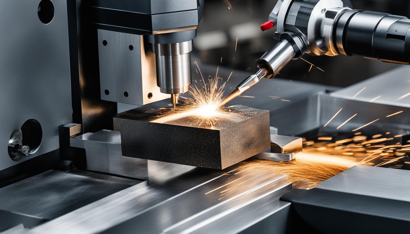
Milling machines are fundamental to subtractive manufacturing, capable of transforming raw material into complex components through precise material removal. These versatile machines utilize rotating multi-point cutting tools to perform a wide array of operations, from creating flat surfaces to intricate three-dimensional contours.
Modern CNC milling machines offer unparalleled accuracy and repeatability, making them indispensable across industries like aerospace, automotive, and medical device manufacturing. Understanding the specific operations a milling machine can execute is crucial for optimizing part design and production efficiency.
Face Milling Flat Surfaces
Face milling is a primary operation used to produce flat, smooth surfaces on a workpiece, often serving as a reference plane for subsequent machining. This process typically employs a face mill, which has cutting inserts on its face and periphery, to remove material from the top surface of the part.
Effective face milling requires careful consideration of cutter diameter, insert geometry, and cutting parameters. A larger cutter diameter generally allows for higher material removal rates and better surface finishes, as it distributes the cutting load over more inserts. Toolpaths for facing usually involve parallel or zigzag patterns to ensure complete coverage and efficiency.
Achievable tolerances for face-milled surfaces can range from ±0.005 inches (±0.127 mm) for standard applications to ±0.001 inches (±0.025 mm) for precision requirements. Surface finish, often measured in Ra (arithmetic average roughness), can be significantly improved with appropriate finishing passes and optimized feeds and speeds.
End Milling Pockets
| Fit Class | Tolerance Designation | Description |
|---|---|---|
| Normal Fit | Js9 | Slight clearance, easy assembly, some backlash acceptable. |
| Tight/Interference Fit | P9 | Press fit, no backlash, for high-precision or reversing-load applications. |
| Loose Fit | D10 | Greater clearance, for applications where easy movement is prioritized. |
Pocket milling involves removing material from within a defined boundary to create recessed cavities or internal features in a workpiece. These pockets can be flat-bottomed, stepped, or contoured, depending on the part’s design.
Toolpath strategies for pocketing are critical for efficiency and tool life. Traditional methods often involve a series of deep, heavy cuts, while high-efficiency milling (HEM) strategies utilize lighter radial depths of cut, heavier axial depths of cut, and higher feed rates to spread heat and wear across more of the cutting edge.
Internal corner radii are a significant design consideration in pocket milling. Since cylindrical end mills leave a radius, specifying sharp internal corners often necessitates smaller tools, slower feed rates, and increased cycle times. Designing internal corner radii 10% to 20% larger than the cutting tool radius can prevent dwelling and chatter.
Typical tolerances for milled pockets range from ±0.003 to ±0.005 inches (±0.076 to ±0.127 mm), though tighter tolerances down to ±0.001 inches (±0.025 mm) are achievable with light finishing passes, rigid tooling, and shallow pockets.
Drilling and Rigid Tapping
Milling machines are fully capable of performing drilling operations to create holes in workpieces. Various drill bits are selected based on material, hole diameter, and depth. Peck drilling strategies are often employed for deeper holes to aid chip evacuation and prevent tool wear.
Rigid tapping, a highly precise threading operation, is also commonly performed on CNC milling machines. This process synchronizes the spindle rotation with the axial feed rate, ensuring that the tap’s pitch is accurately maintained as it cuts threads into a pre-drilled hole. This synchronization is crucial for producing high-quality threads.
Hole tolerances for drilled features typically fall within ±0.002 inches (±0.050 mm), with reaming capable of achieving tighter tolerances around ±0.0005 inches (±0.0127 mm). For tapping, thread pitch is usually held to a Class 2B standard fit, with Class 3B used for tighter, more critical applications.
Slotting Keyways
Slotting keyways is a specialized milling operation to create rectangular grooves in shafts or hubs, essential for transmitting torque between mating components. Keyway milling cutters are specifically designed for this task, often featuring two symmetrical cutting edges for stability and accuracy.
Unlike standard end mills, keyway cutters can plunge axially, similar to a drill, which allows them to process closed slots or flat-bottom grooves. For optimal accuracy and productivity, keyway slotting is often divided into two steps: roughing with an undersized end mill, followed by a finishing pass to achieve true square corners.
Standard keyway dimensions and tolerances are defined by standards such as ANSI B17.1 for inch-series keys and DIN 6885 or ISO 773 for metric keys. For metric systems, Js9 tolerance provides a normal fit, allowing for easier assembly, while P9 tolerance results in a press fit for applications requiring no backlash.
Profile Contour Machining
Profile contour machining involves moving a cutting tool along a defined contour or programmed path to generate intricate shapes, edges, and faces of a workpiece. This method is crucial for manufacturing parts with complex curves, angles, and three-dimensional surfaces requiring high precision.
Contour milling can range from 2D profiling along external or internal boundaries to complex 3D surface contouring, often seen in mold making, aerospace components, and turbine blades. Multi-axis machines, particularly 5-axis systems, significantly enhance contouring capabilities by allowing the tool to approach the workpiece from virtually any angle in a single setup.
The benefits of 5-axis simultaneous contouring include increased accuracy, superior surface finishes, and reduced machining times due to fewer setups and continuous tool engagement. This capability minimizes tool marks and improves overall part quality, often reducing the need for post-processing.
Profile milling can hold tolerances up to ±0.001 inches (±0.025 mm) or better under well-controlled conditions, especially with advanced CAM software and optimized toolpaths. Achieving these tight tolerances often requires multiple finishing passes and careful control over cutting parameters to manage tool deflection and workpiece stability.